 Threads
A solid mid-tower case.
Review Summary
The Thermaltake View 32 mid-tower case stands out with its stylish design, four tinted tempered glass panels, and vibrant RGB fans at a reasonable price. While it’s a great choice for enthusiasts seeking visual appeal and spacious interiors, it may not be budget-friendly. Despite minor challenges like the top panel attachment, the View 32 delivers a satisfying building experience, making it an attractive option for those prioritizing both aesthetics and performance.
Hours Tested: 8-10

Overall
-
Performance - 8/10
8/10
-
Features - 8/10
8/10
-
Design - 9/10
9/10
-
Value - 7/10
7/10
Pros
- Visually Stunning Design
- RGB Lighting
- Spacious Interior
- 3 Pre-installed fans
Cons
- Limited Fan Speed Control
- Not Budget-Friendly


Thermaltake recently came out with their new View series chassis named Thermaltake View 32 which raises the bar for mid-tower cases with four 4mm thick tinted tempered glass panels and Thermaltake’s RGB fans (3 of them), all this at an attractive price point. Without further a due, let’s dig in and see what this chassis has to offer to the builder.
Key Takeaways
- The Thermaltake View TG RGB is perfect for those looking for a well-built mid-tower case that provides several tempered glass panels as well as preinstalled RGB fans.
- The Thermaltake View TG RGB is not for those working with a lower budget.
- The Thermaltake View TG RGB comes with three pre-installed fans, tempered glass panels, as well as a contemporary design that will fit most modern builds.
- Why you can trust Tech4Gamers: Our reviews are based on dedicated hands-on testing by our team of experienced hardware experts. Find out more about how we test.
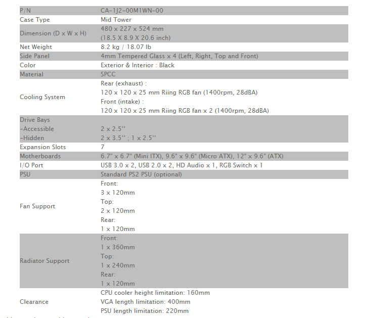
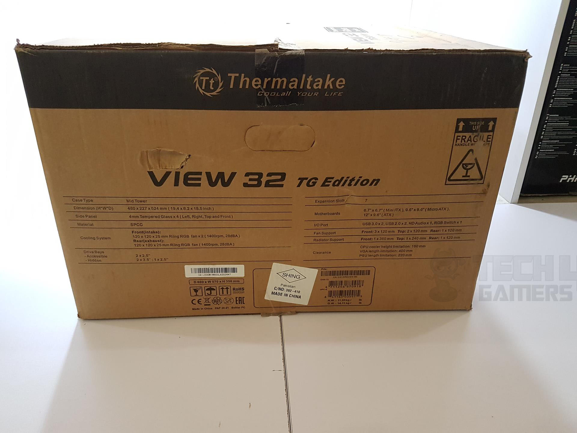
Here are the detailed specifications of the Thermaltake View 32.
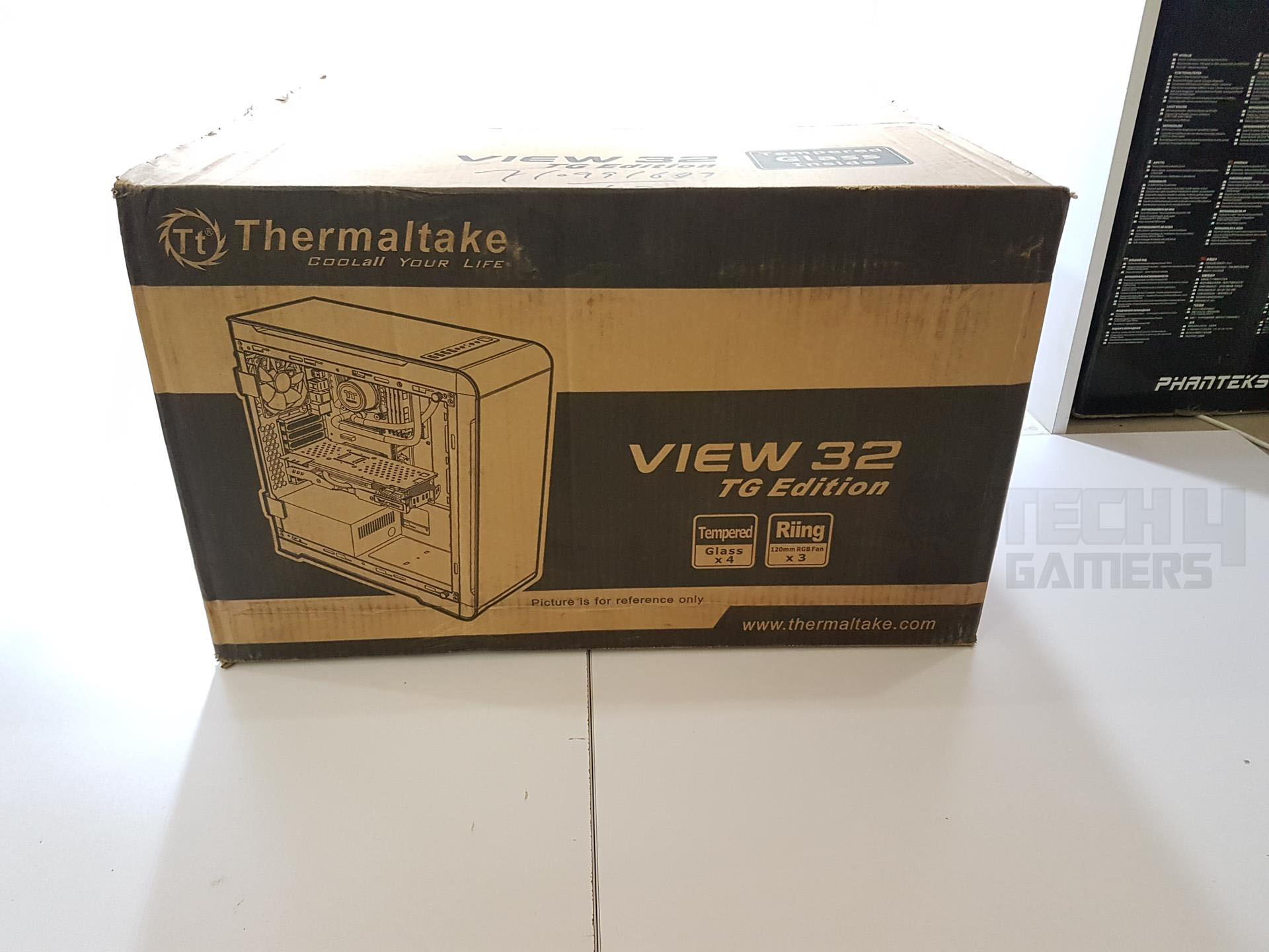
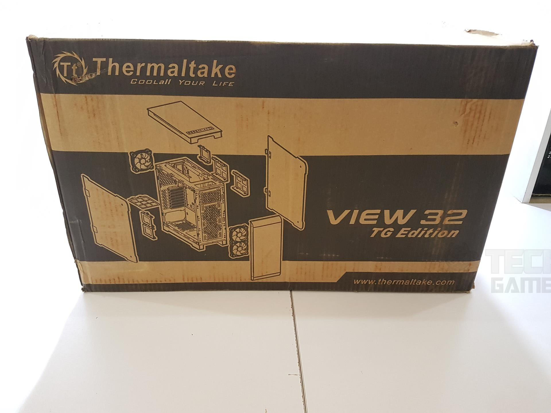
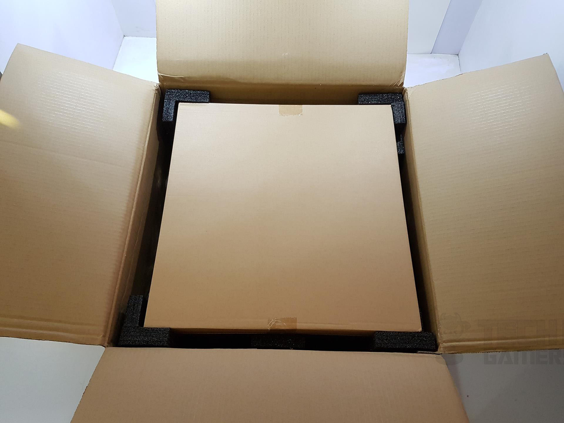
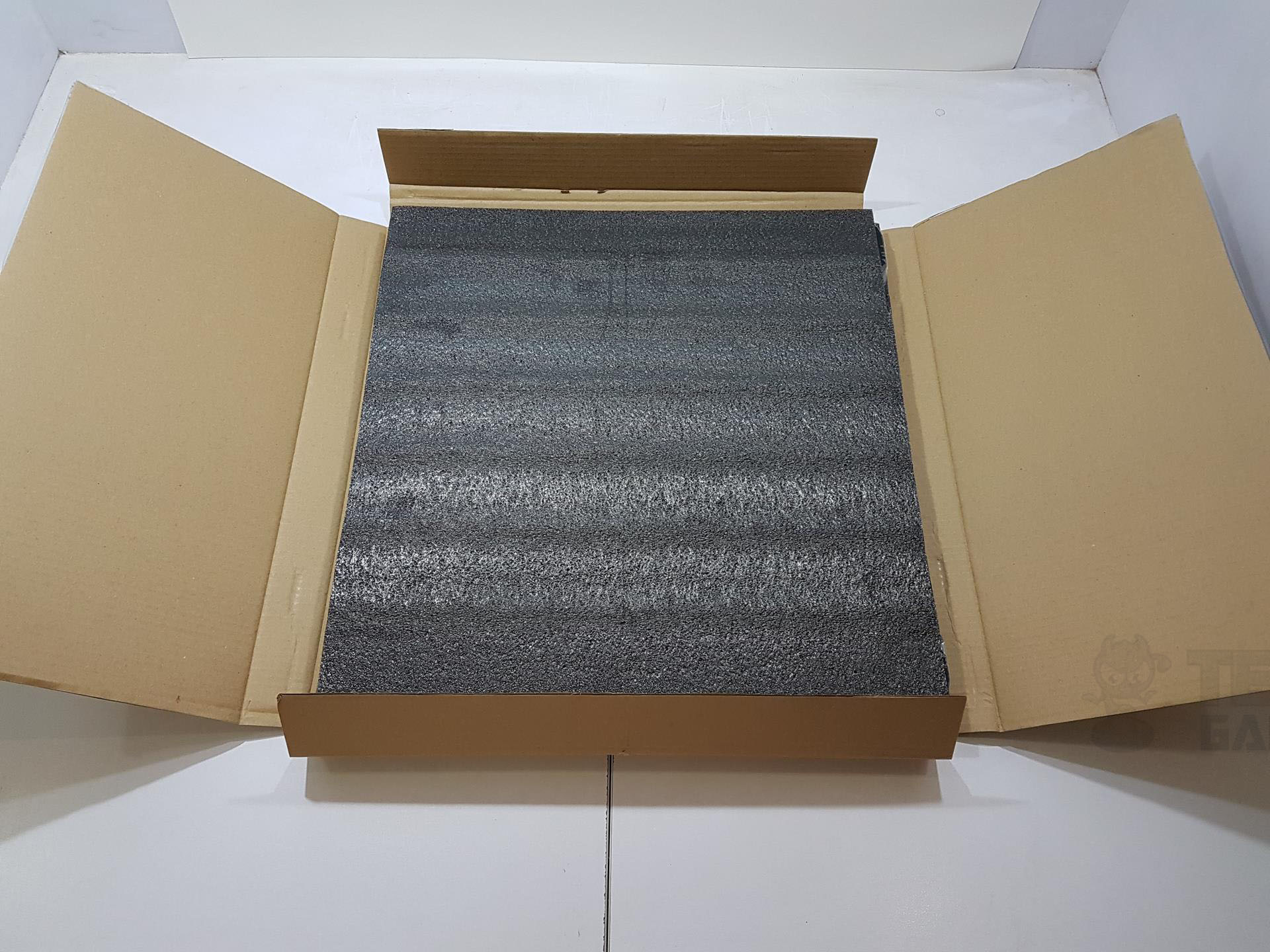
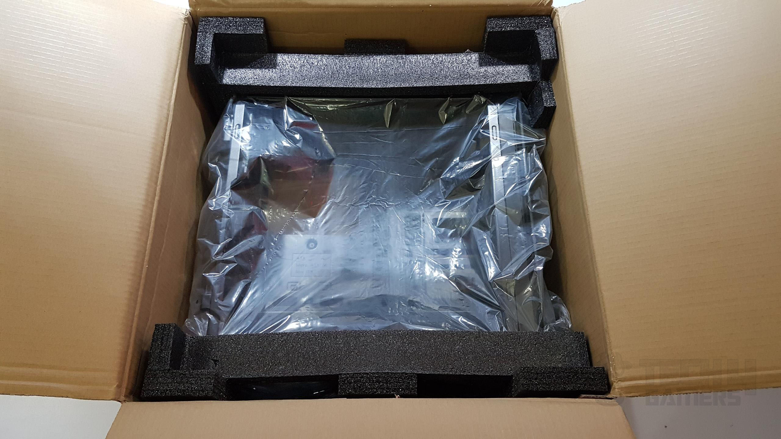
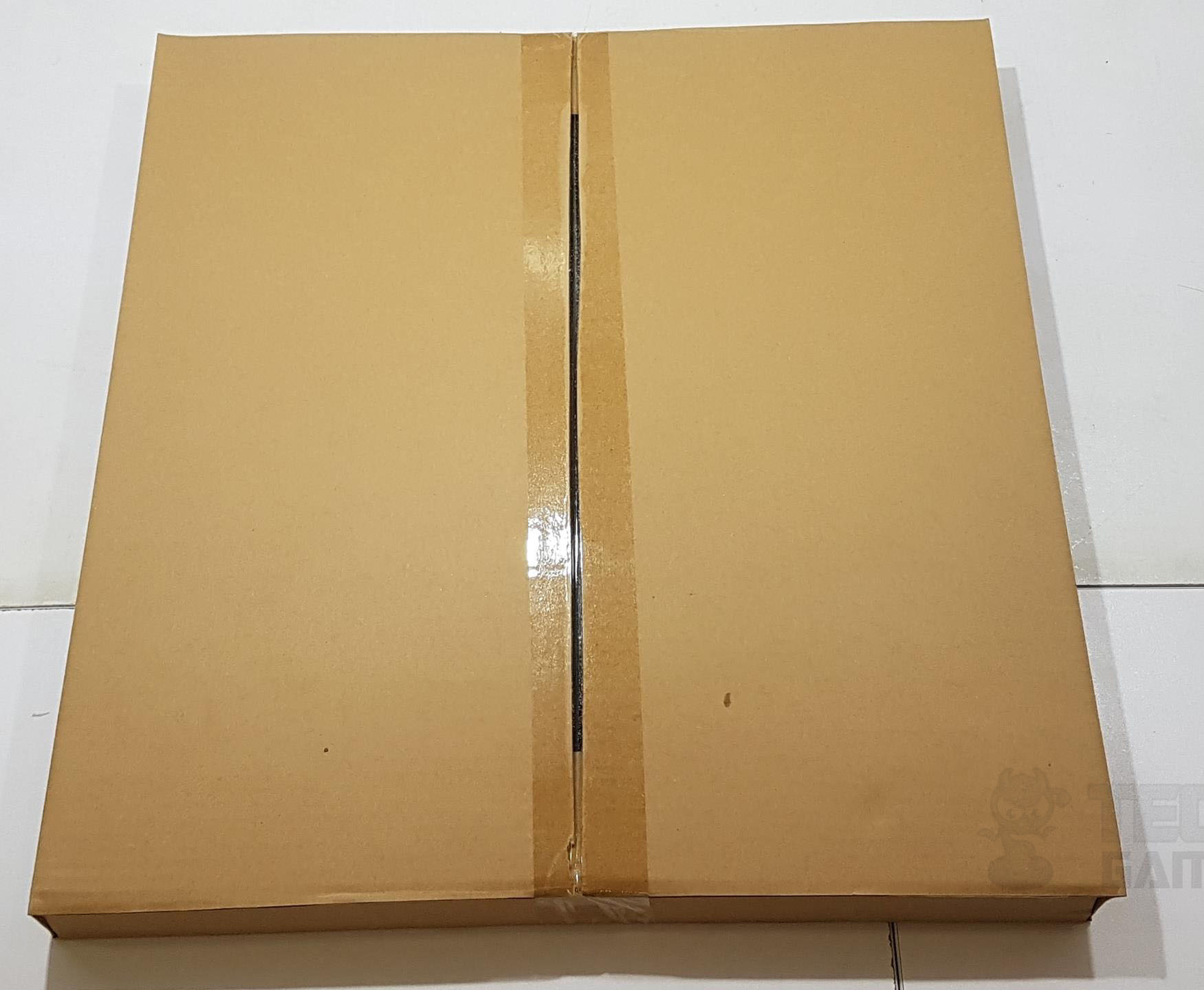
Packaging and Unboxing
Let’s begin with the unboxing experience.


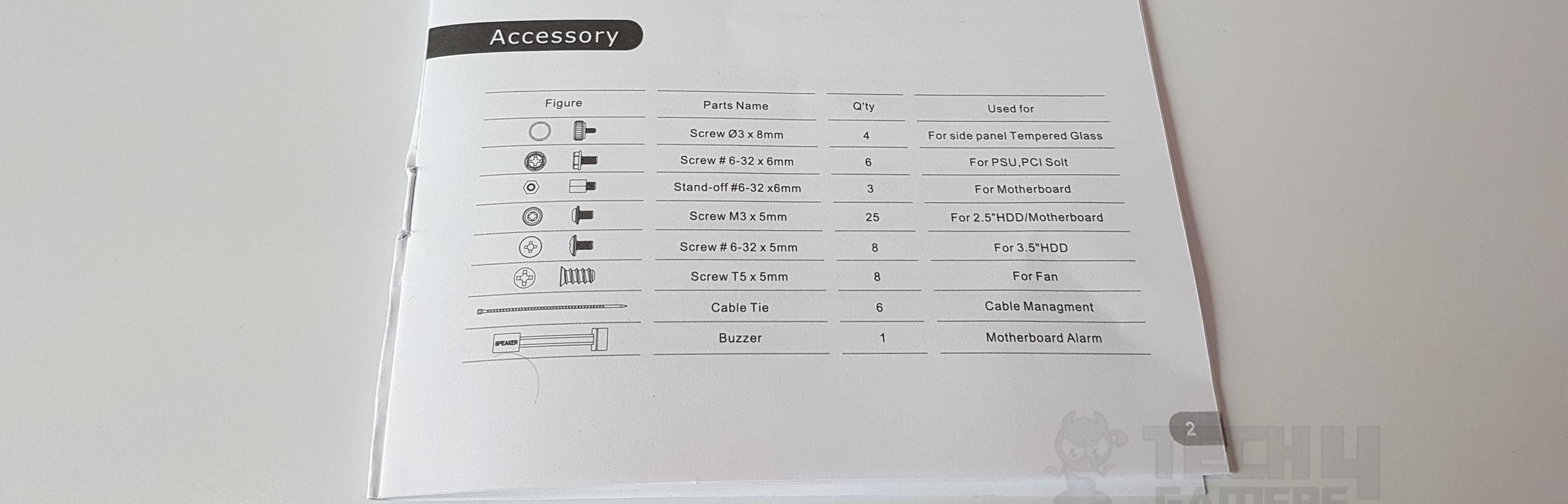
Accessories
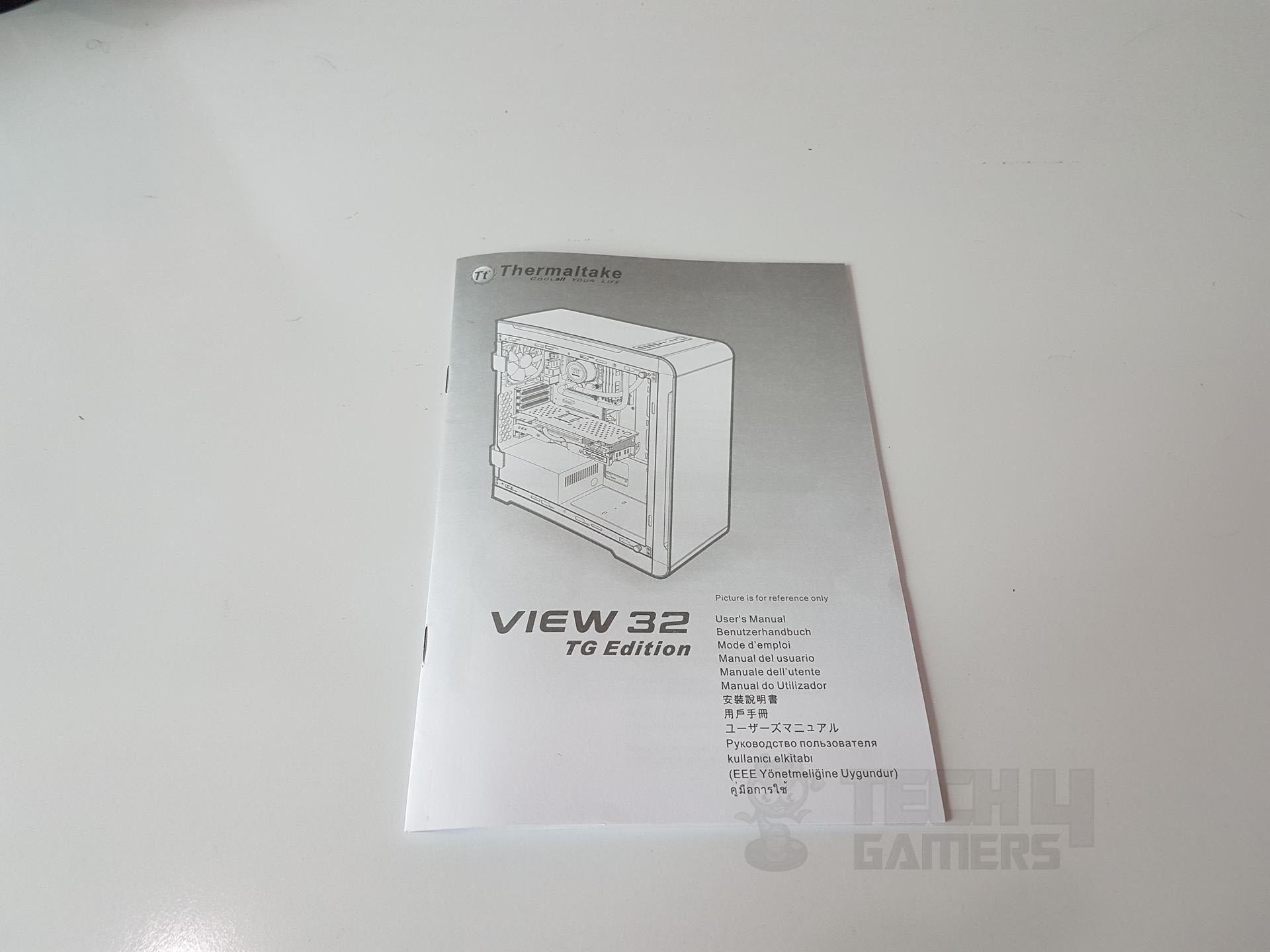
We have the accessories list and the manual.
Closer Look
It is time to dig into the design elements of this chassis.
Interior
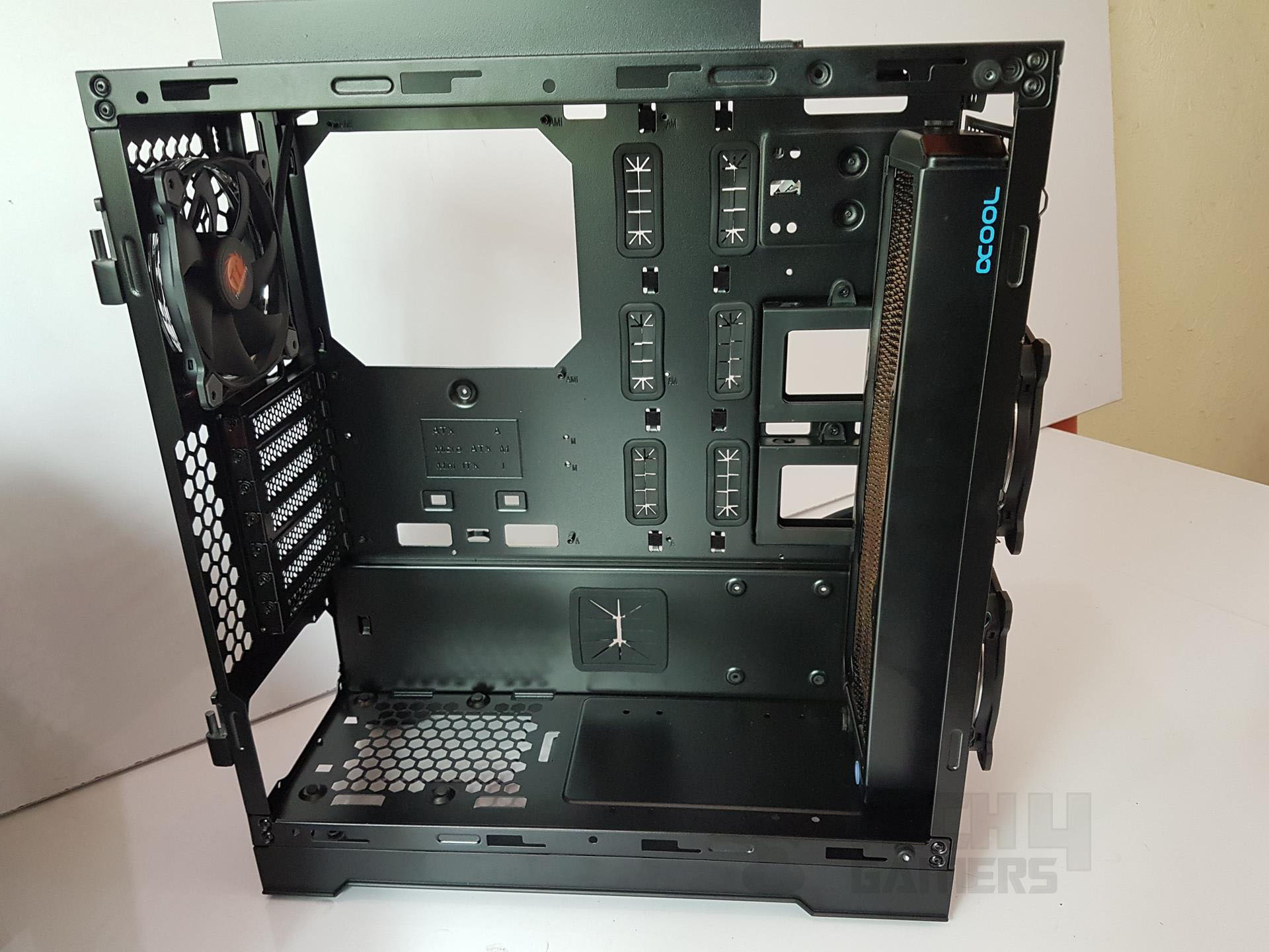
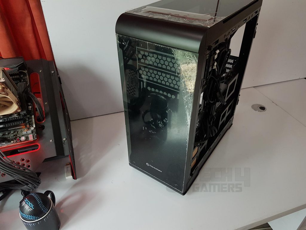
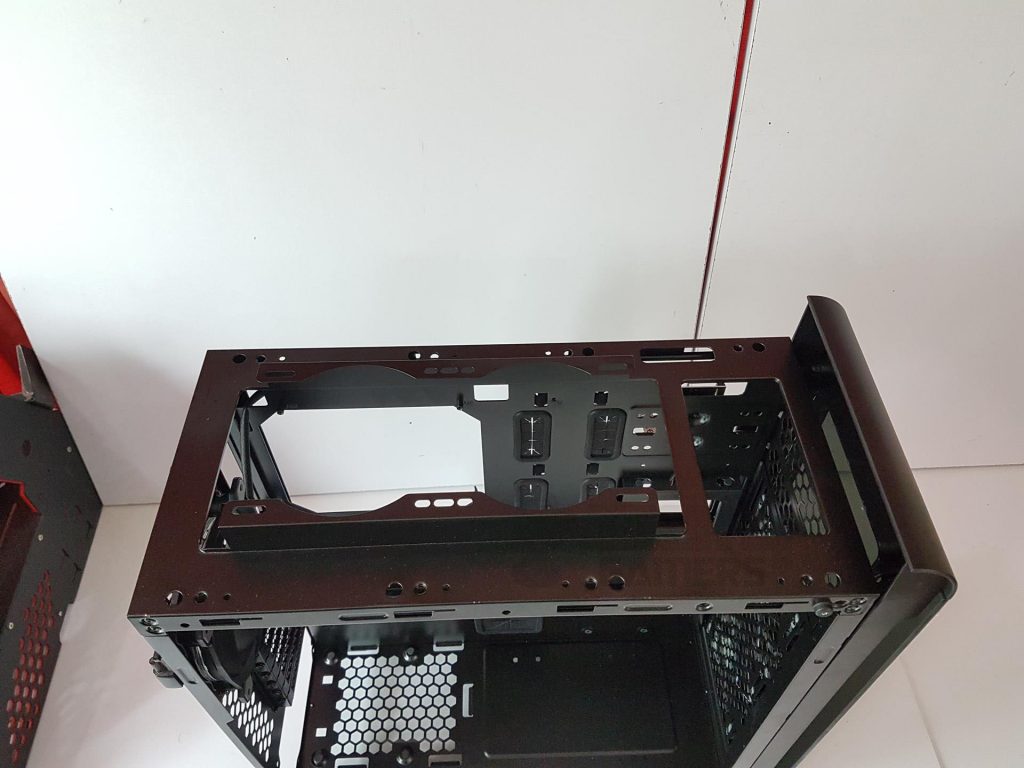
The Thermaltake View 32 has dimensions of 480x227x524mm, featuring a black SPCC material build with two preinstalled tempered glass panels on the top and front. The left and right panels are provided separately, contributing to a stunning and well-coordinated design when all four tempered glass panels are installed.
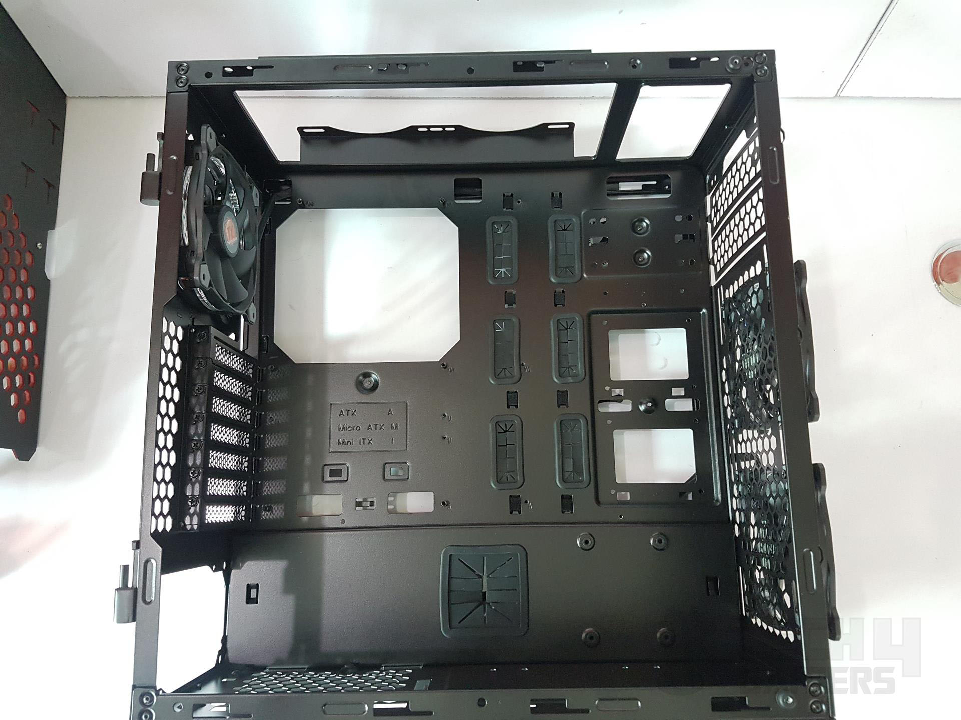
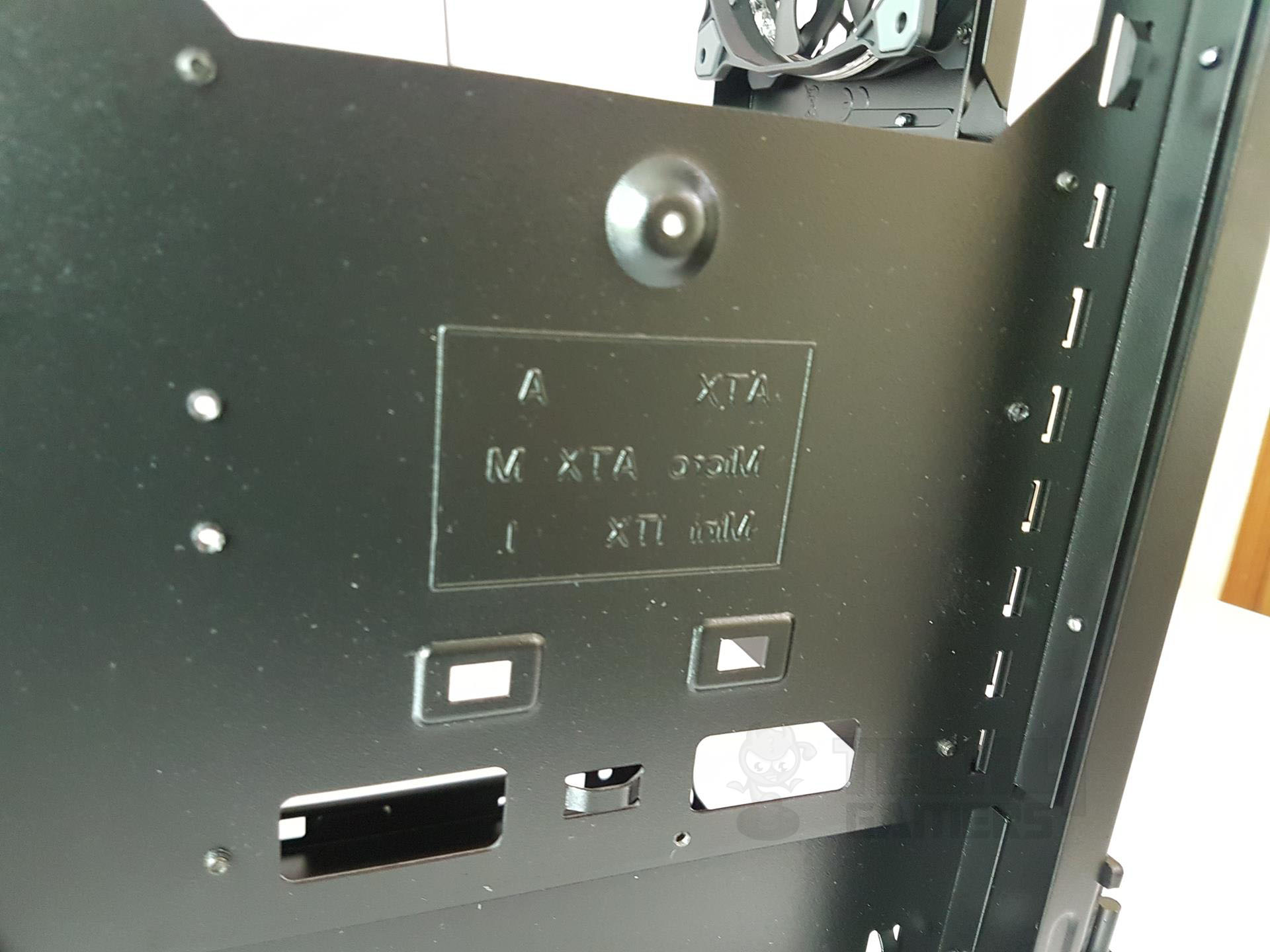
The spacious chassis accommodates ATX, microATX, and mini-ITX motherboards. However, only 6 out of 9 standoffs are pre-installed. A large CPU cutout with a 160mm clearance is present on the motherboard tray. Two small, non-grommeted cutouts above and around the CPU area lack rubber coverings. Below the CPU cutout, a screw secures a 2.5″ drive caddy behind the tray. Motherboard tray holes are labeled A (ATX), M (microATX), and I (mini-ITX). Learn more about motherboard form factors.
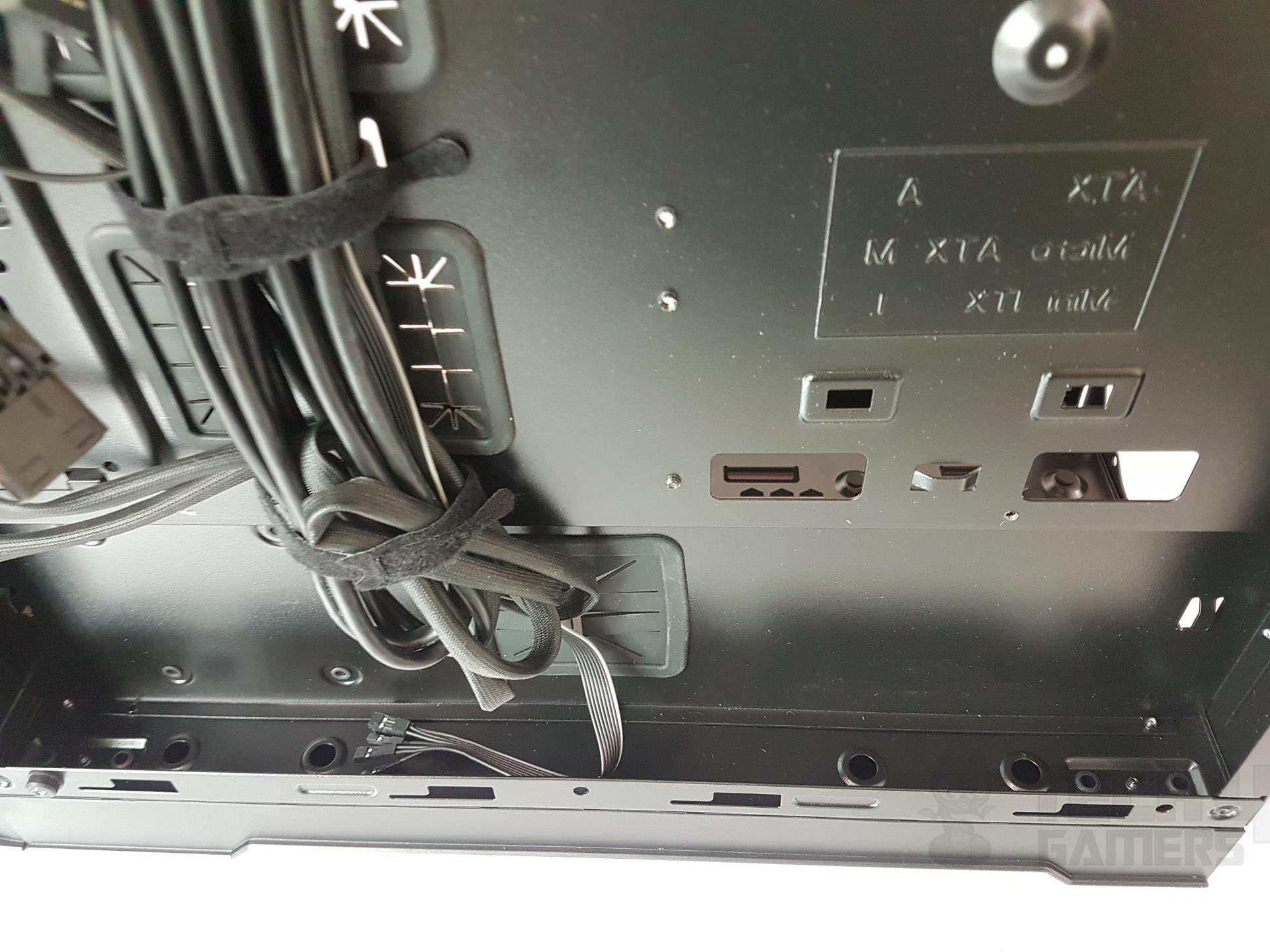
Two bottom cutouts lack rubber grommets and can be covered when using a full ATX motherboard, potentially impacting cable routing for bottom headers.
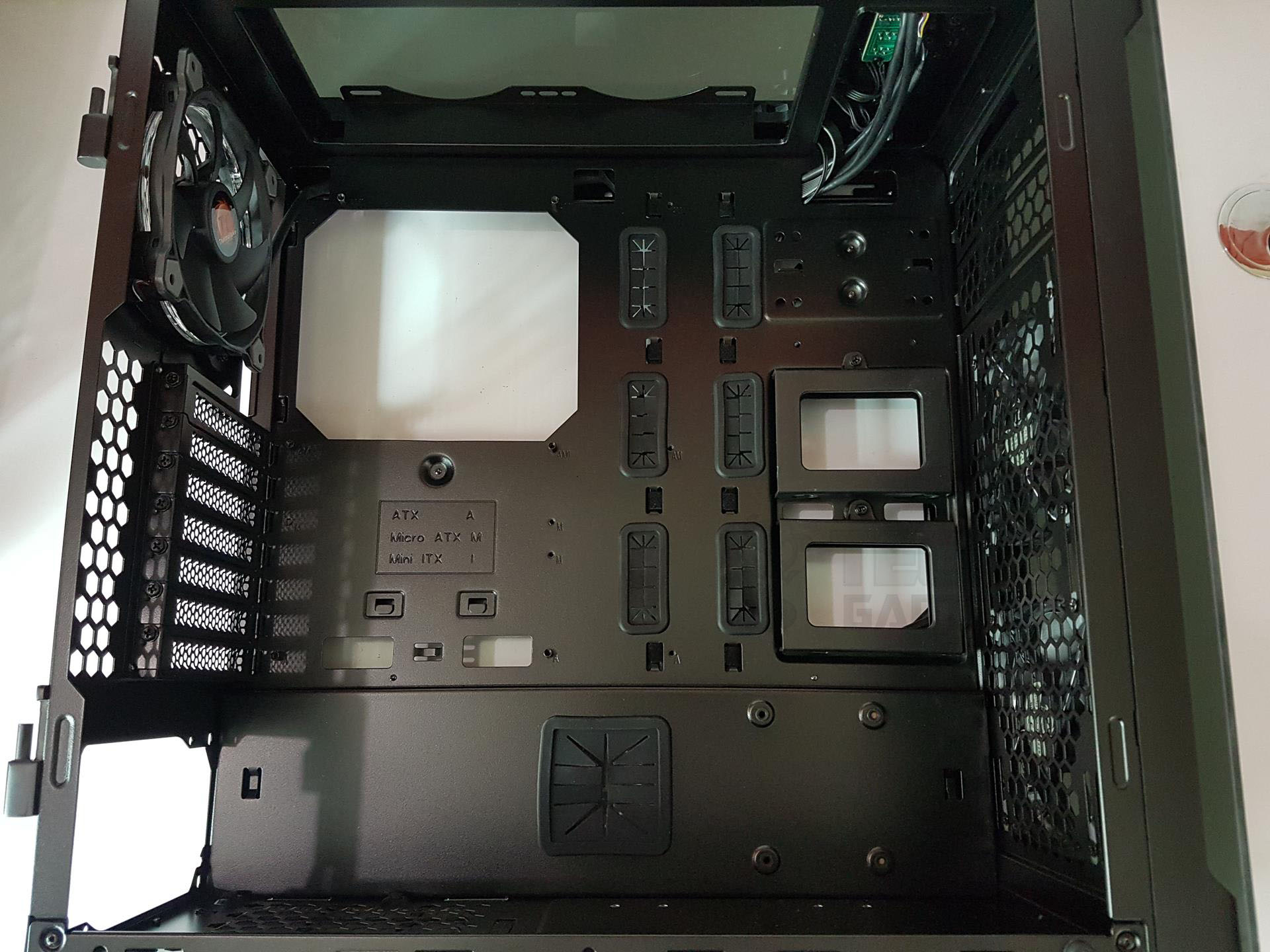
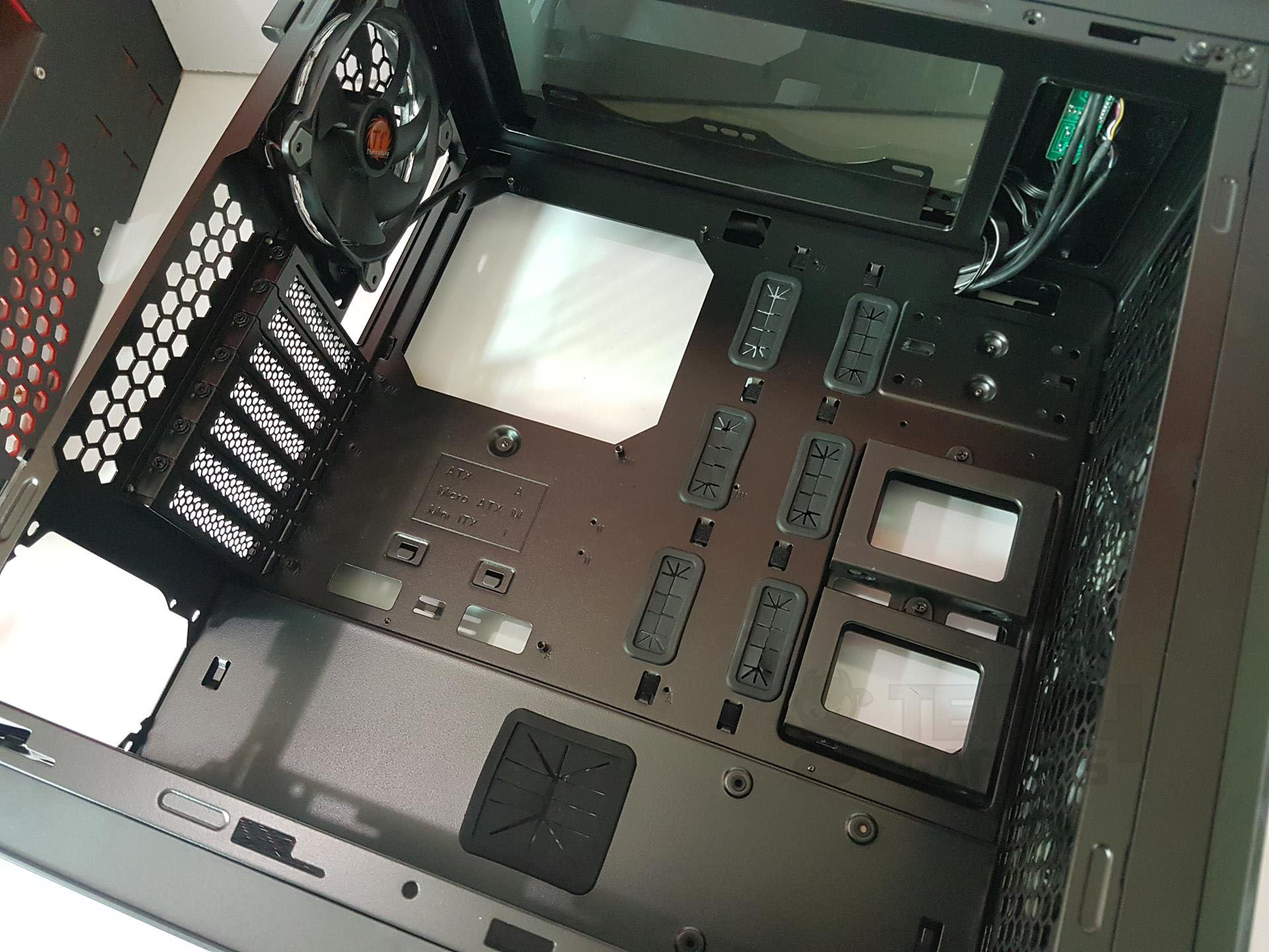
The motherboard tray features two columns of cutouts with rubber grommets, totaling 6. With a full-size ATX board, only the rightmost three cutouts are accessible for cable routing. The right end of the tray houses two 2.5″ drive caddies. If unused, the exposed backside could be visible, although the tinted back panel provides some cover.
The top section of the tray has a raised surface for the included Controller Hub installation. Seven PCIe covers with mesh design lack thumb screws, requiring a screwdriver. A pre-installed Riing RGB fan with 256 colors is on the top rear, and its cable is routed through the top left cutout. Moving to the bottom section.
On the left side, there’s a PSU mount area with a filtered bottom intake/exhaust. Four raised tabs with rubber mounts support the PSU, allowing for up to 220mm PSU clearance. A central cutout with a rubber grommet assists with cable management, but caution is needed to prevent the grommet from coming off under slight pressure from cables.
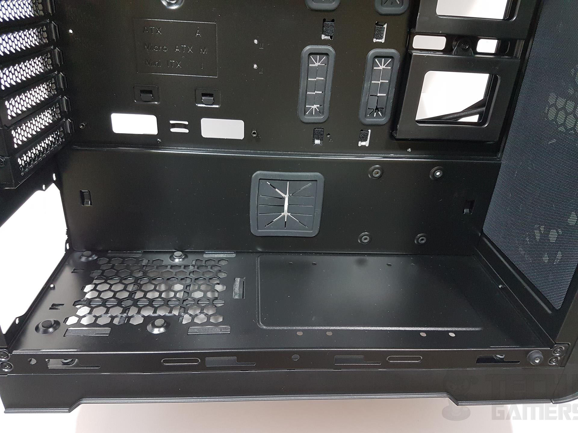

The PSU area accommodates any large-sized PSU, but if it exceeds 220mm, the cutout becomes inaccessible for cable routing. The View 32 is a smaller counterpart to the View 71, and design limitations are apparent. For those requiring up to 360mm clearance on the top, the View 71 is recommended. The raised radiator bracket on View 71 provides better displacement from the top to the motherboard, offering improved clearance for high-profile RAM (roughly 55mm).
Although not full, View 32 allows adjustment of the radiator/fan position, but accessing the top side of the bracket for installation requires removing both the top and side panels. The method of attaching these panels to the chassis frame is an unusual choice.
There are four raised latched hooks on each side of these panels. One would need to press the two bars on each and at the same time pull the panel. While doing this, one constantly remains under the impression that he/she might break the glass as glass is fixed to the panel.
I wish they had handled the panels’ connection to the frame differently. This is made further difficult for the top panel as these latches are hard to reach on the backside. Take your time and be careful while removing the panels.
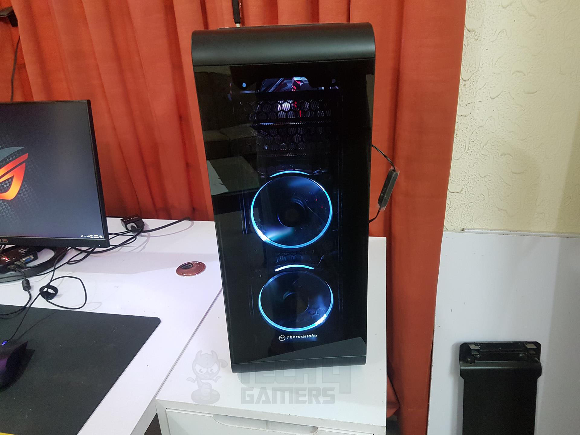
Front
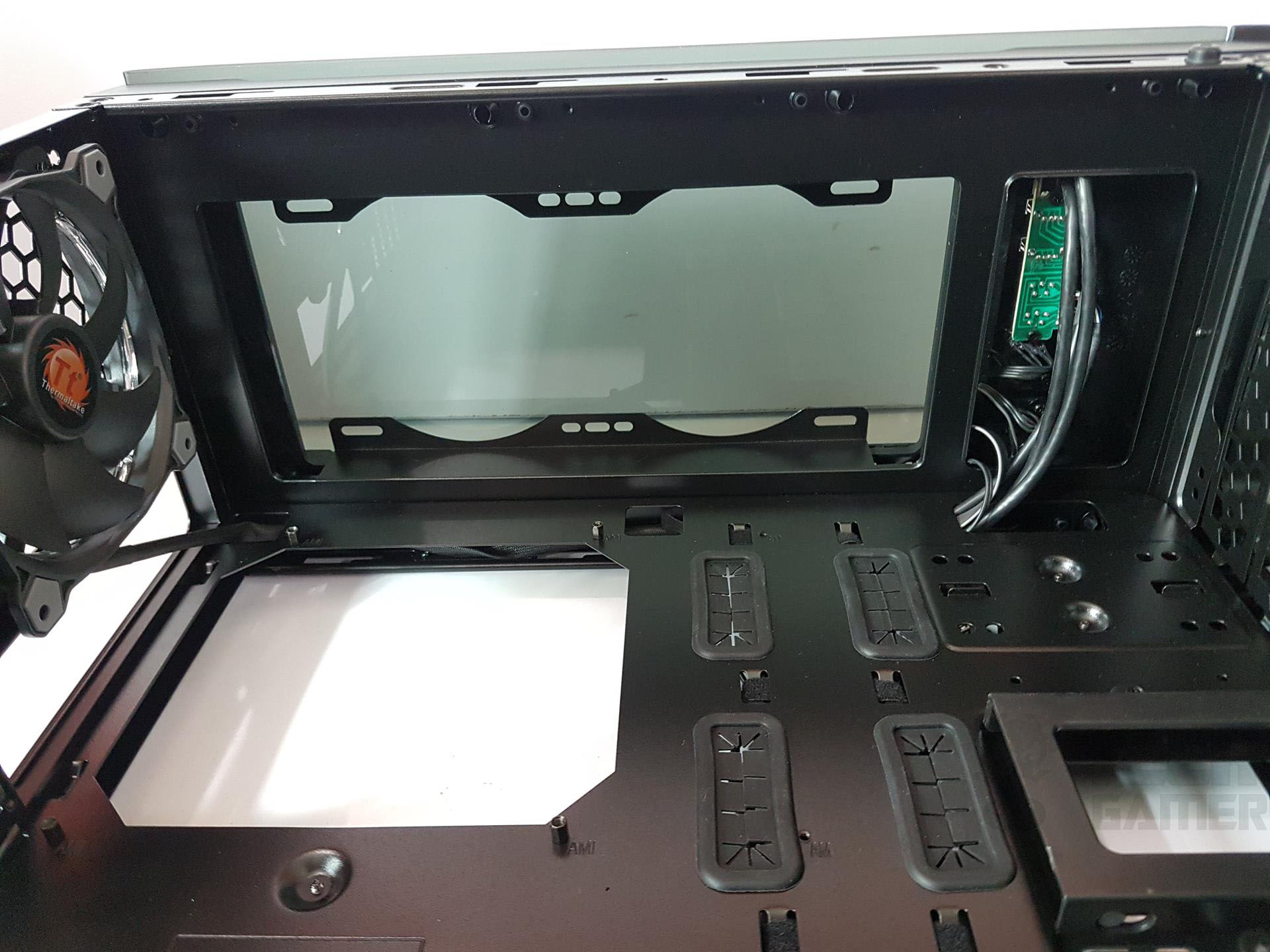
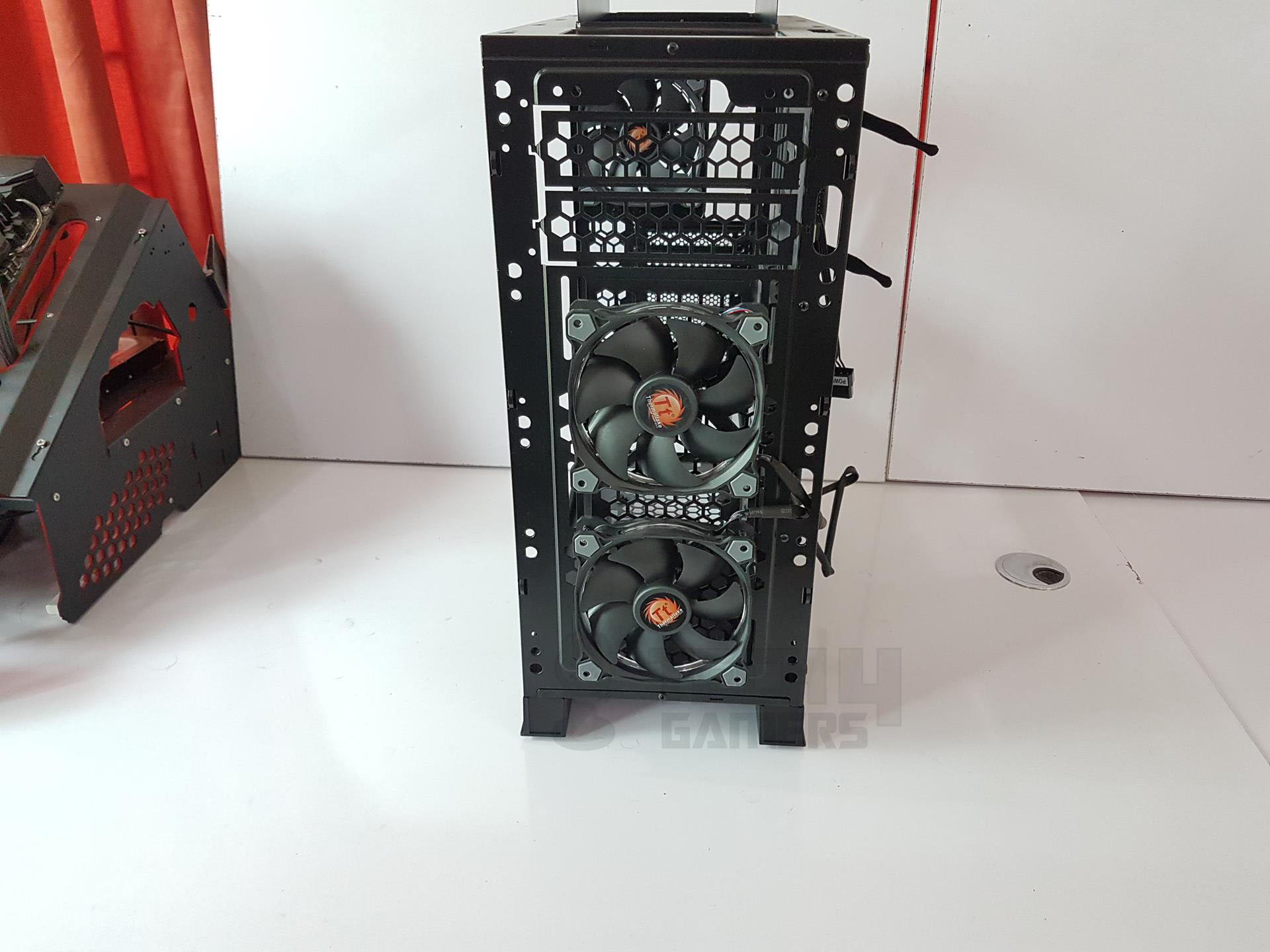
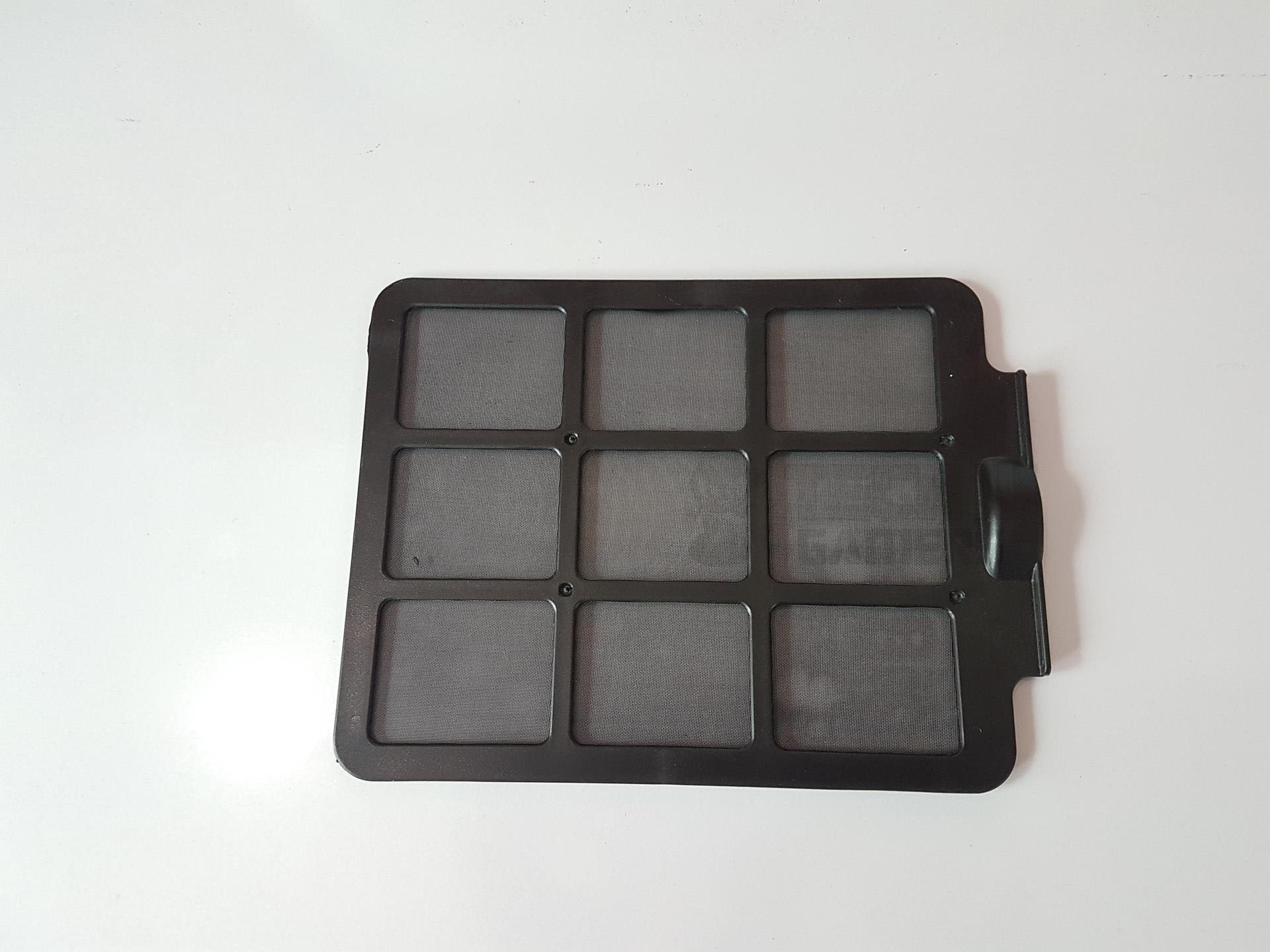
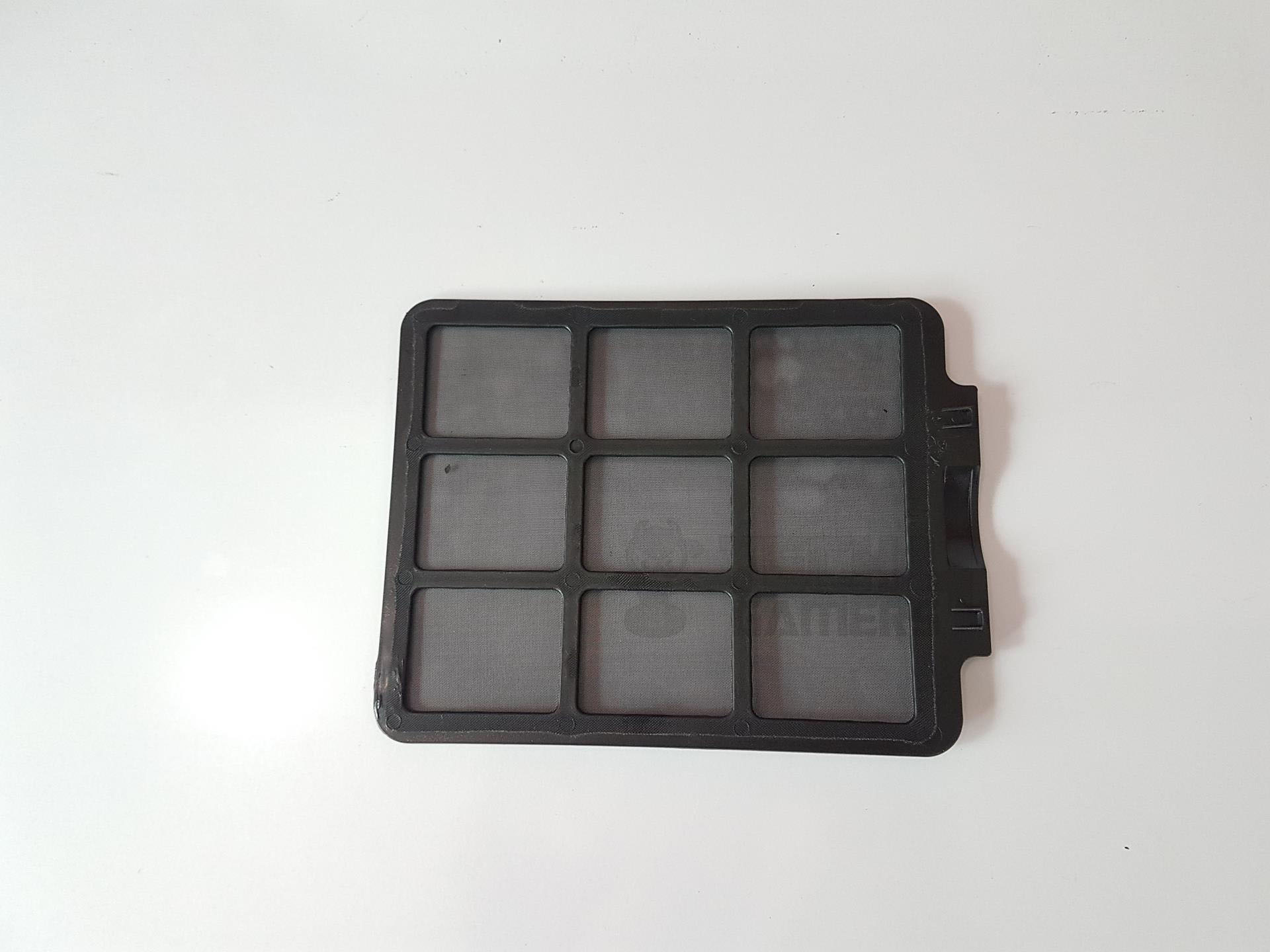
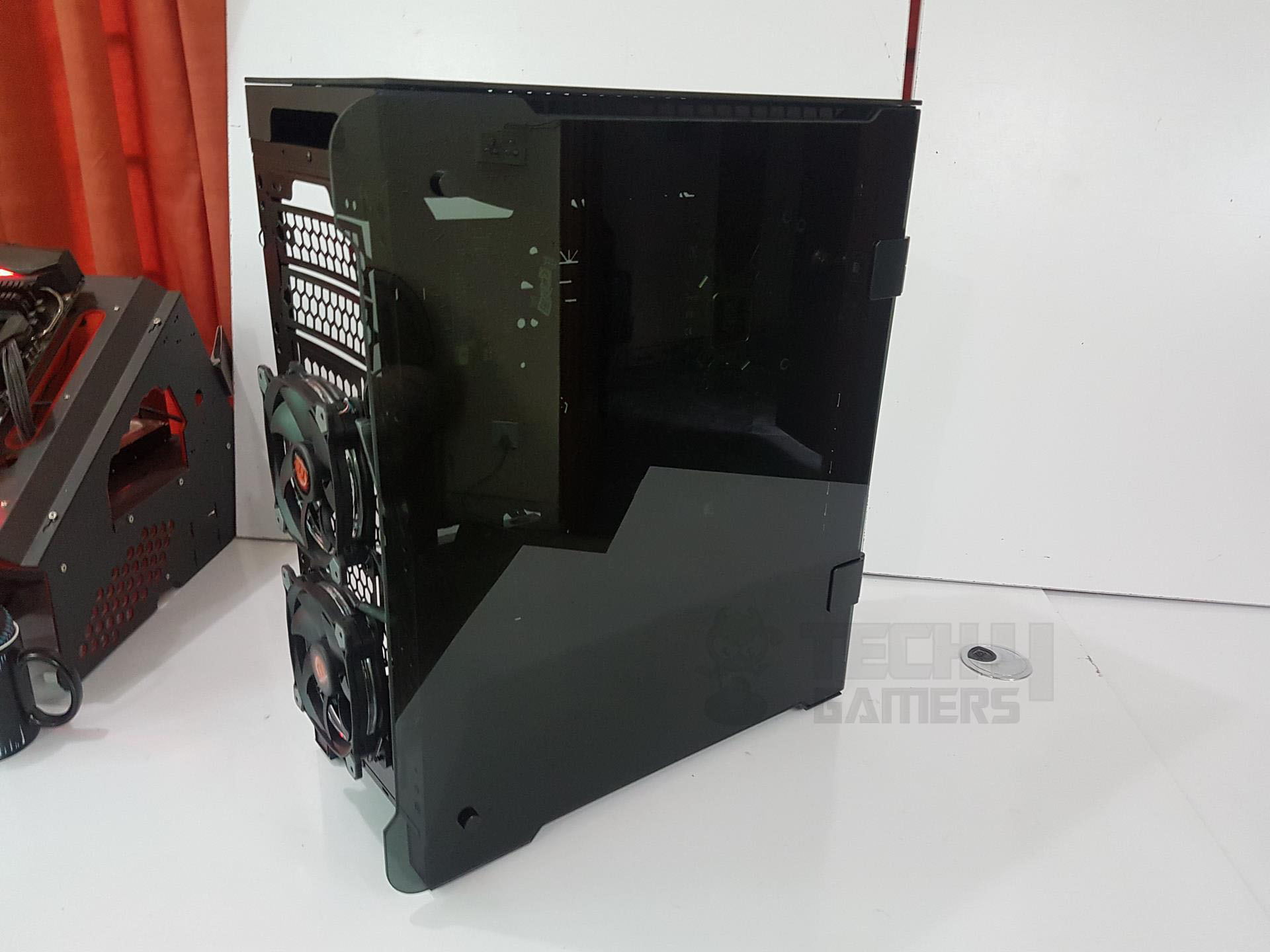
The interior of the chassis reveals a large magnetic dust filter covering the entire front length. It’s high-quality and easy to handle due to its magnetic nature. Removing the filter exposes two preinstalled Riing RGB fans positioned in front of the mesh, secured with screws from the backside. To access the fans, the front panel needs to be removed.
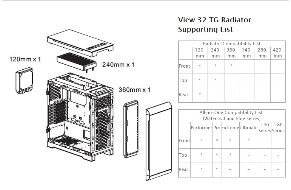
There are two loose covers on the top that may appear to be for 5.25″ drive bays but aren’t. Be cautious when handling them. During testing, an Alphacool NexXxos ST45, a full copper 360mm radiator with a 45mm thickness without fans, was successfully installed. The SSD caddies did not obstruct the radiator, indicating good design planning
The chassis offers a graphics card clearance of up to 400mm without any front radiator or fan. When installing a radiator or fans, the graphics card clearance needs careful consideration. With a 45mm radiator, there’s 350mm of space for the graphics card. If setting up a reservoir in front of the radiator, this consideration becomes even more crucial.

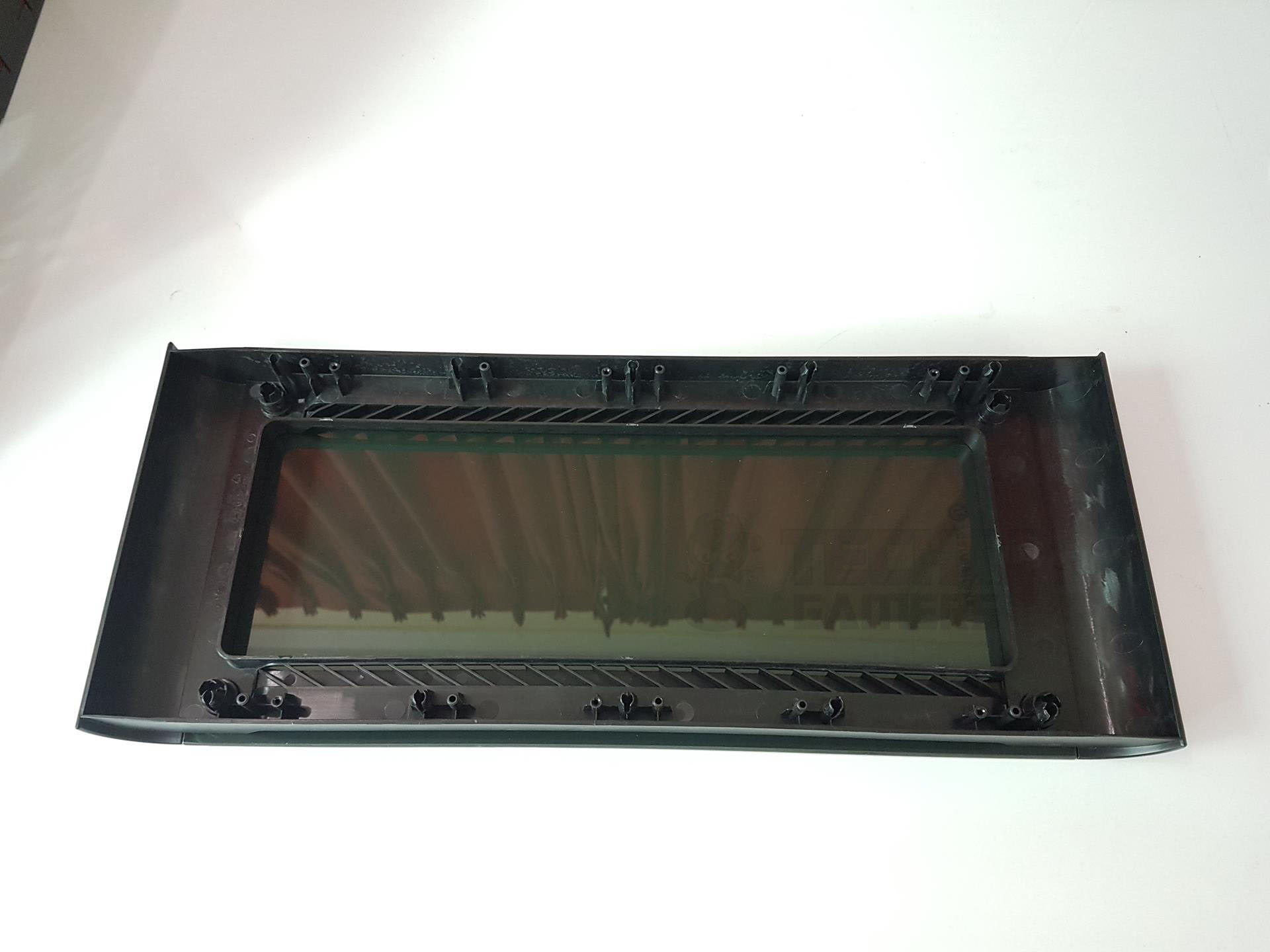
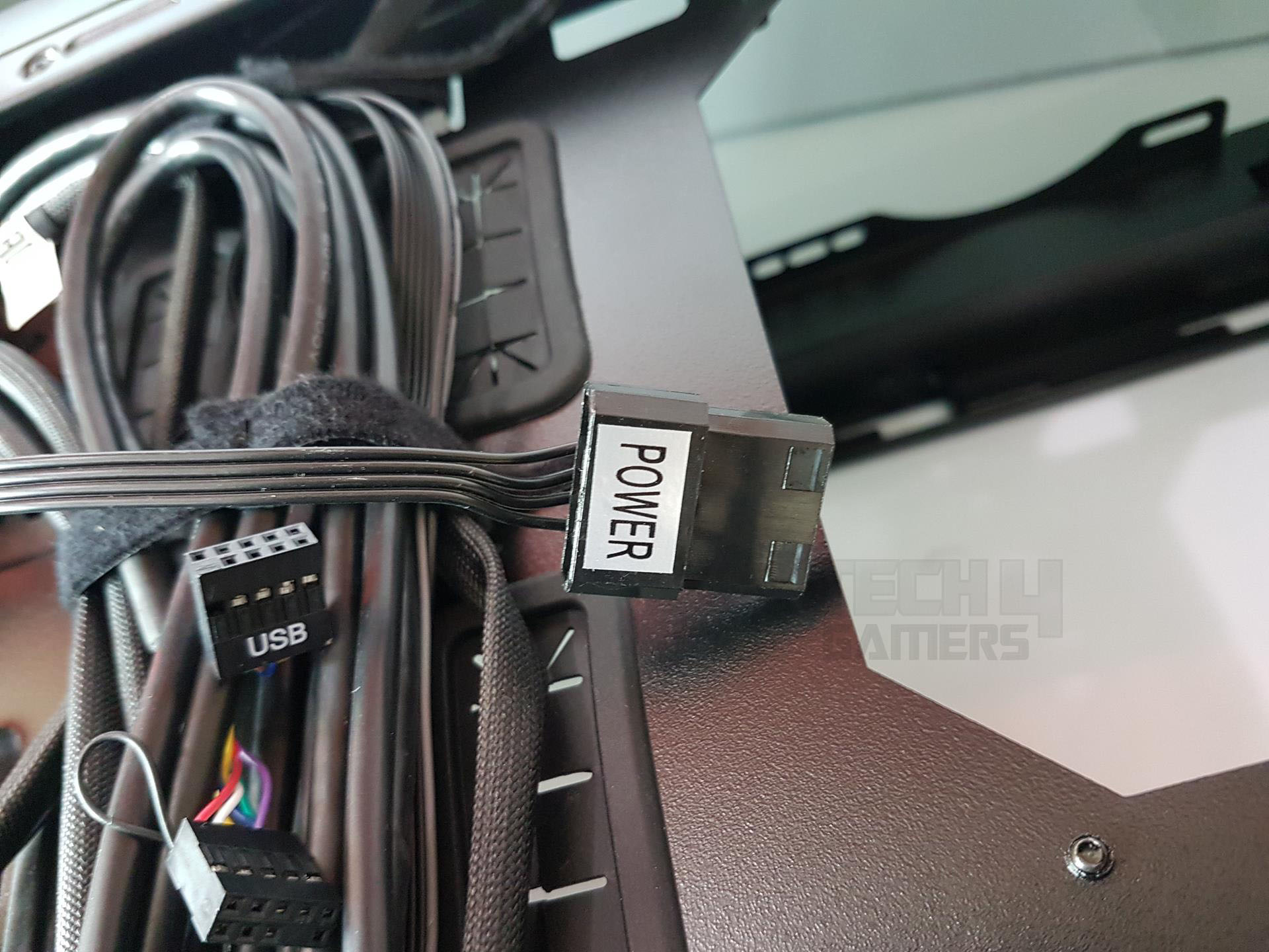
The rounded angular portion is a permanent feature of the front panel’s frame. The front panel is designed such that glass is attached to it on the top of the frame but the only visible section is the one facing the radiator bracket. We have a green color PCB under the front I/O panel. The length of the USB 3.0 connector cable is approximately 805mm. The length of USB 2.0 and HD Audio cables is approximately 940mm (Only the sleeved portion).
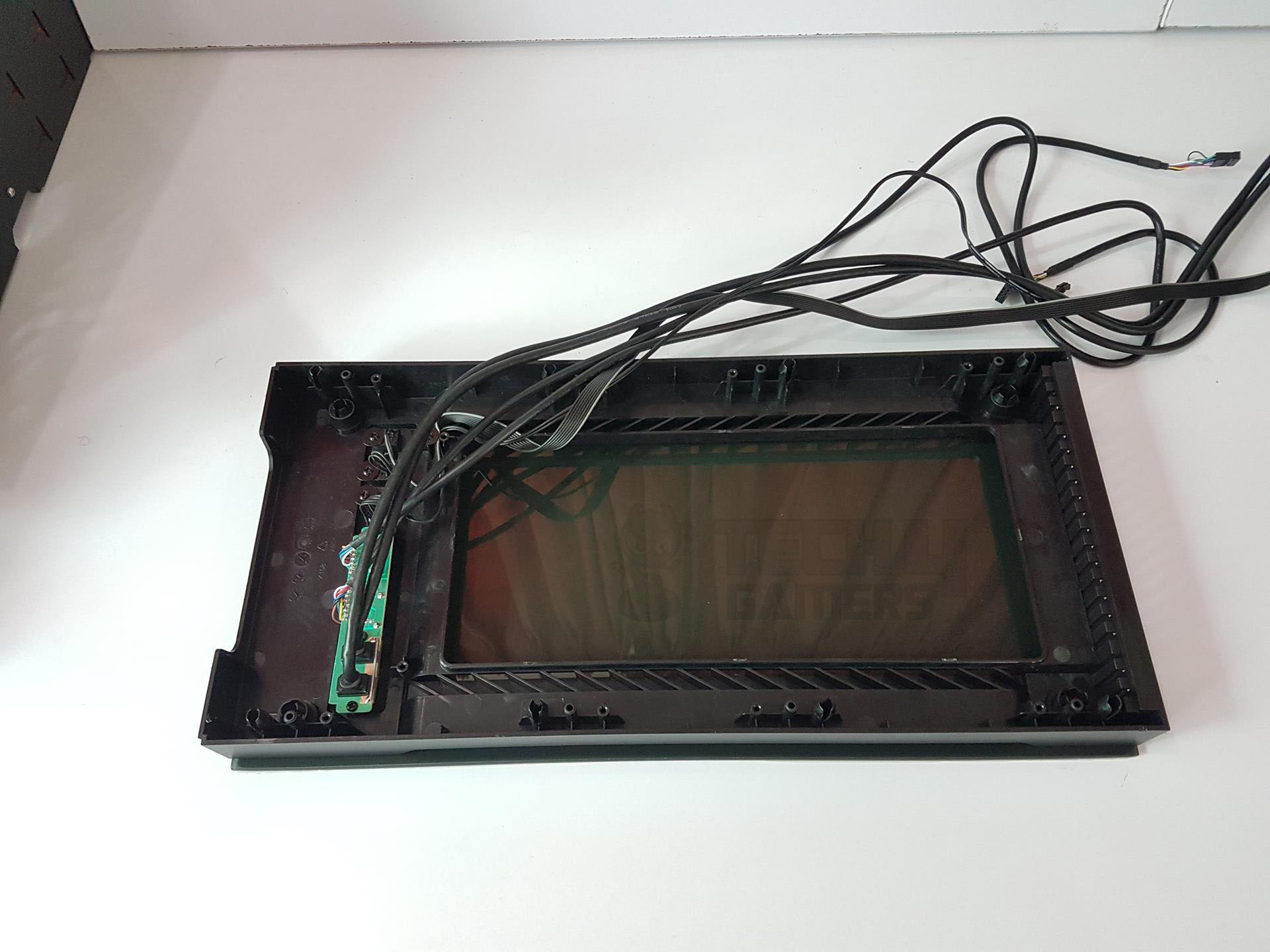
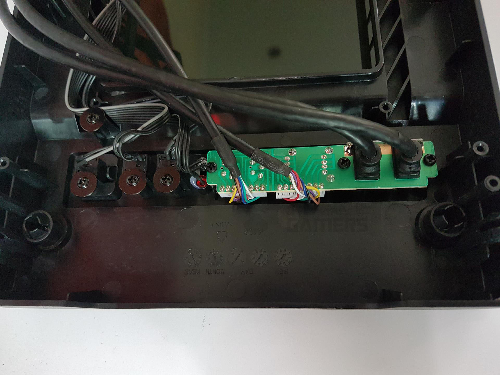
The length of the system panel connector cable is approximately 677mm and the available length of the controller hub cable is approximately 542mm. PCB can be taken off removing the three screws.
Top
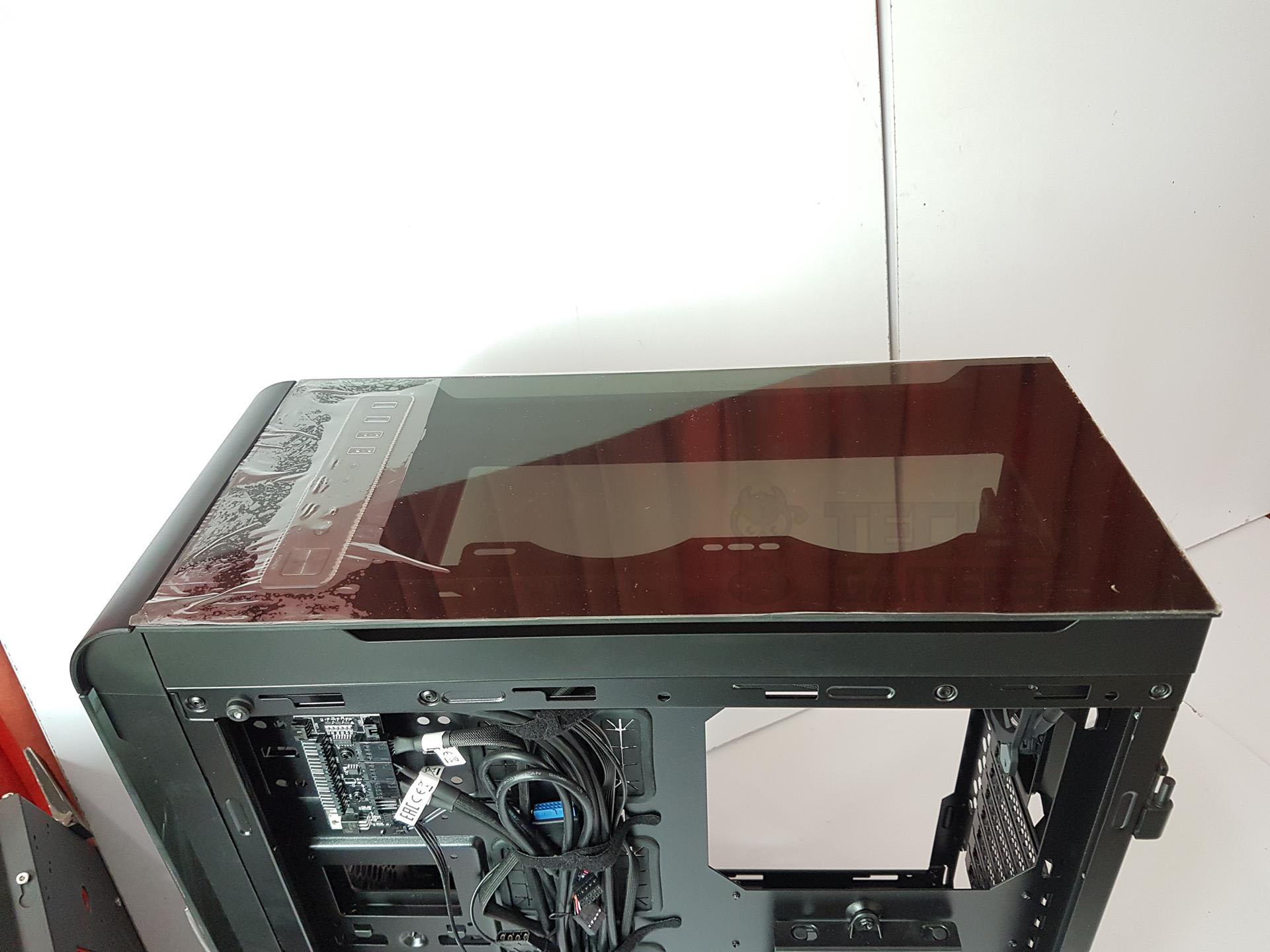
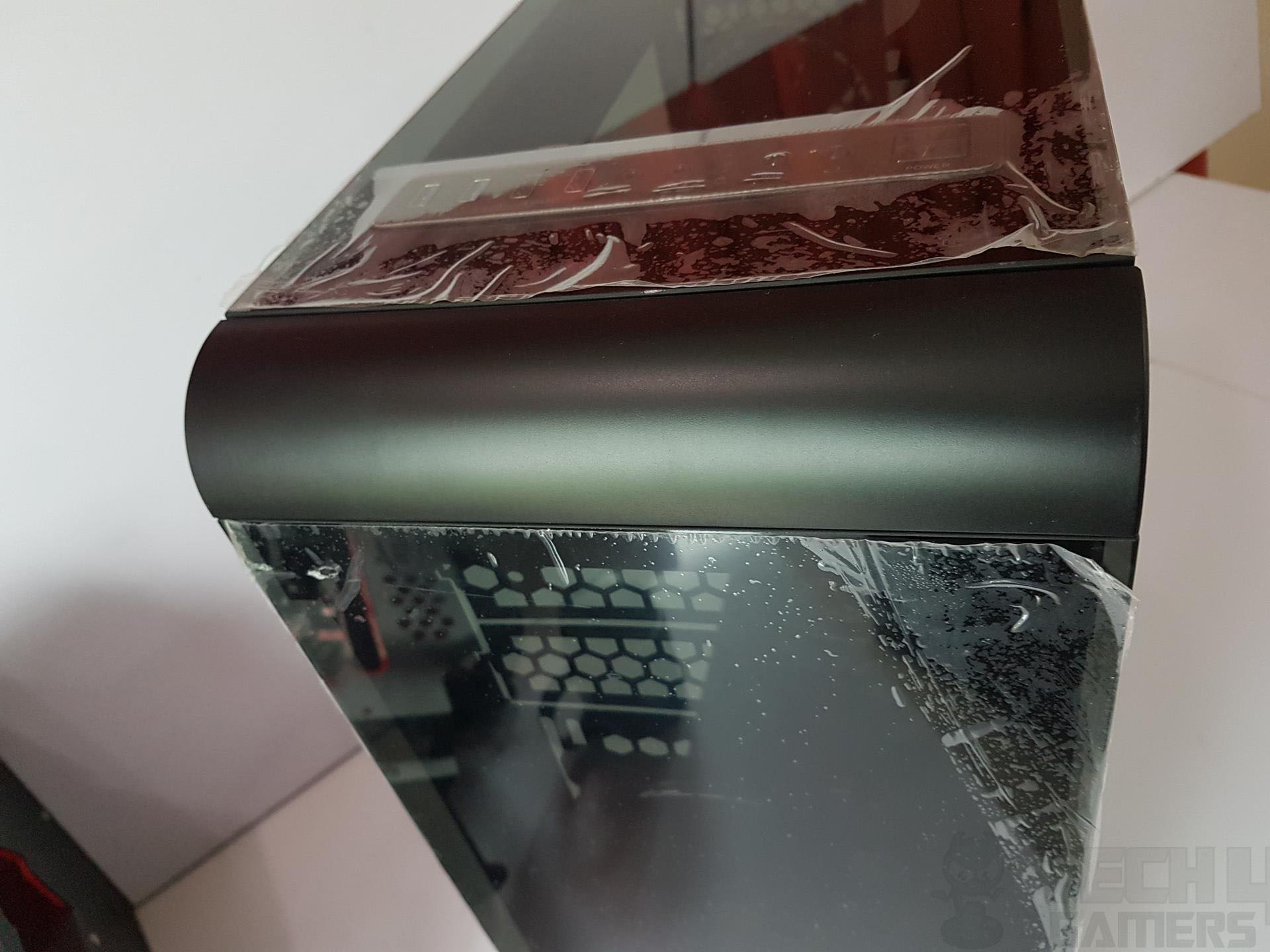
The top panel features tempered glass with air intake vents on the left and right sides of the middle section, directly covering the fans. Despite a 9mm spacing between the glass and the frame, air intake is restricted due to the fans’ proximity to the frame. Placing the fans behind the sheet may help improve airflow.
Let’s take a look at the front I/O panel. It is implemented on the tempered glass with that portion of the glass removed. I must say it is looking that damn good in person than in the pictures. It has a large size square power button with a satisfying tapping experience on button press.
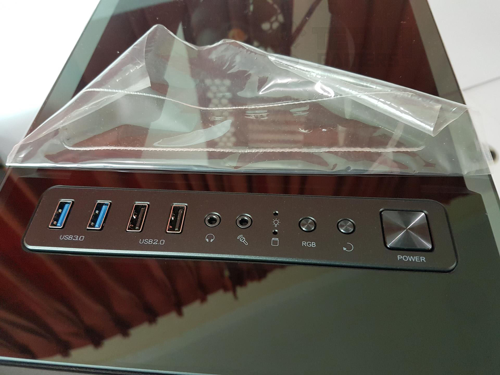
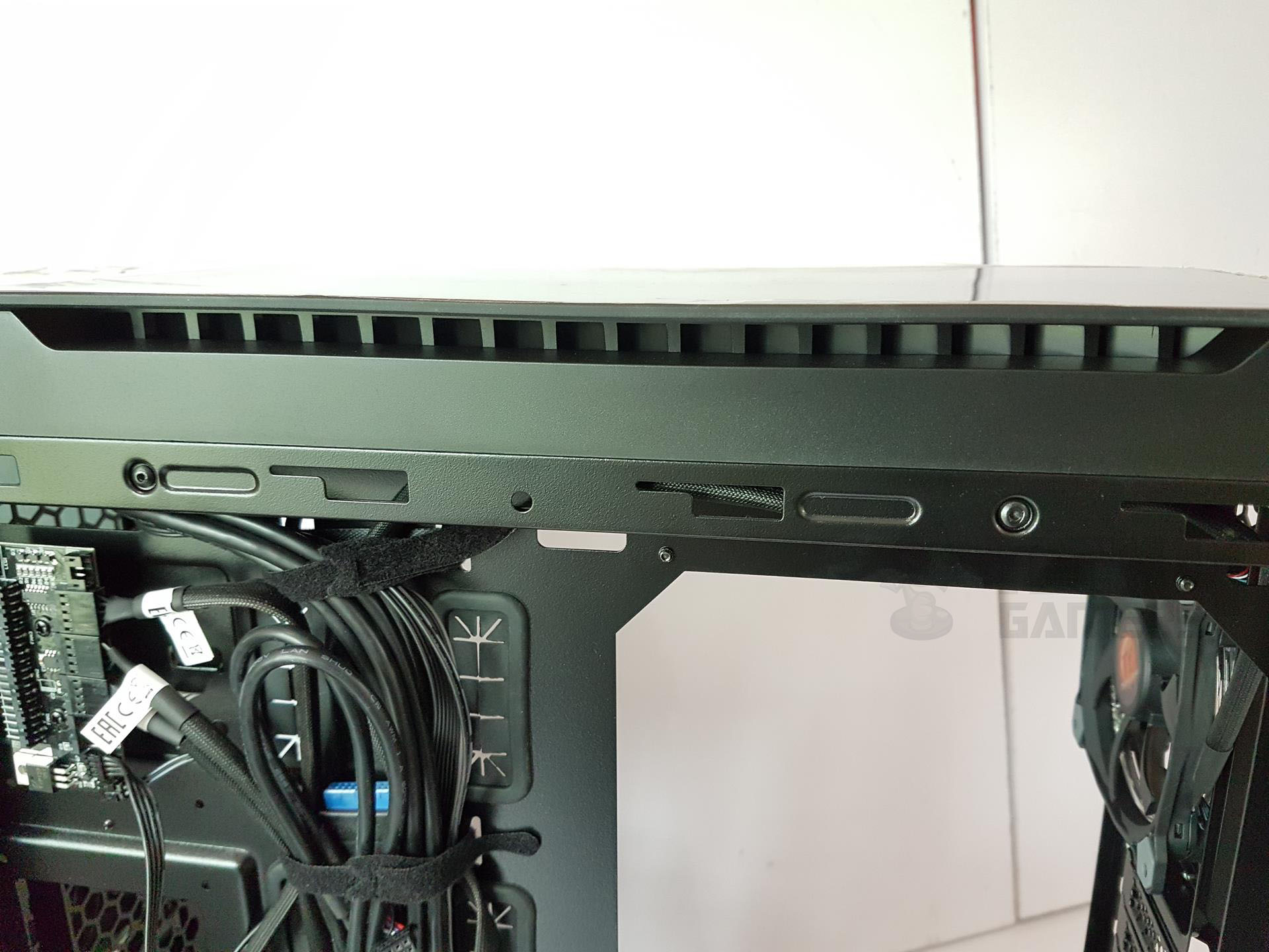
The case features a small Reset button and a circular controller for RGB fan lighting, along with indicator LEDs, headphone and microphone jacks, two USB 2.0, and two USB 3.0 ports. Unfortunately, there’s no USB 3.1 Gen1/2 port. Removing the front panel reveals two pre-installed Riing RGB fans, cable routing cutouts, and mounting holes for a third 120mm fan.
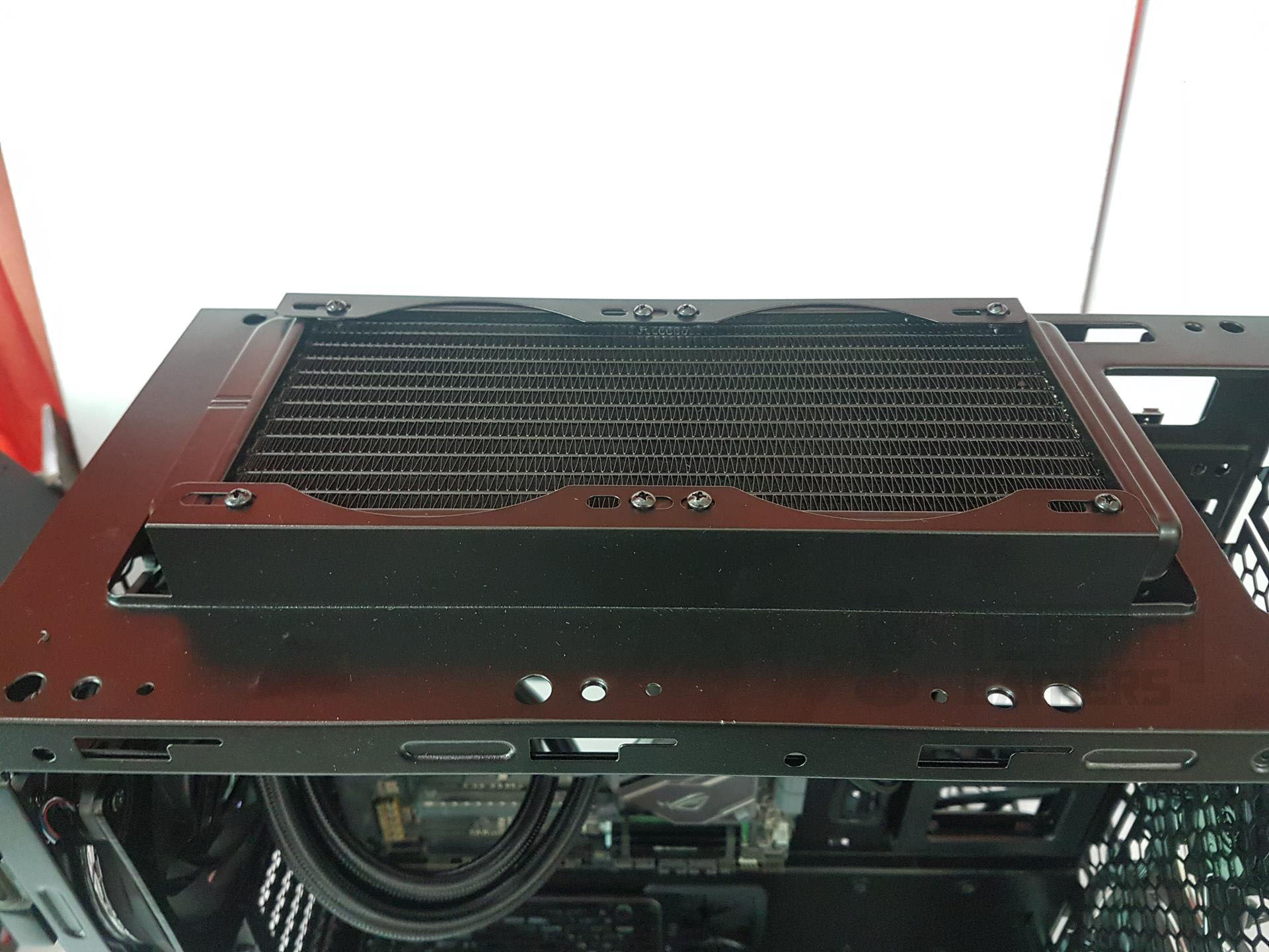
Despite the appearance of 140mm mounts on the rails, they’re obstructed by the front panel design. A large cutout on the tray’s top right side facilitates cable routing behind the motherboard. Last but not least let’s take a look at the top side again from what is visible from inside the chassis. We have a radiator bracket up top with a total height of the bracket being 27mm. We can mount a 120mm or 240mm radiator/AIO on this bracket. With a little bit more depth, Thermaltake View 32 could have provided provision for the 280mm radiator.
Rear
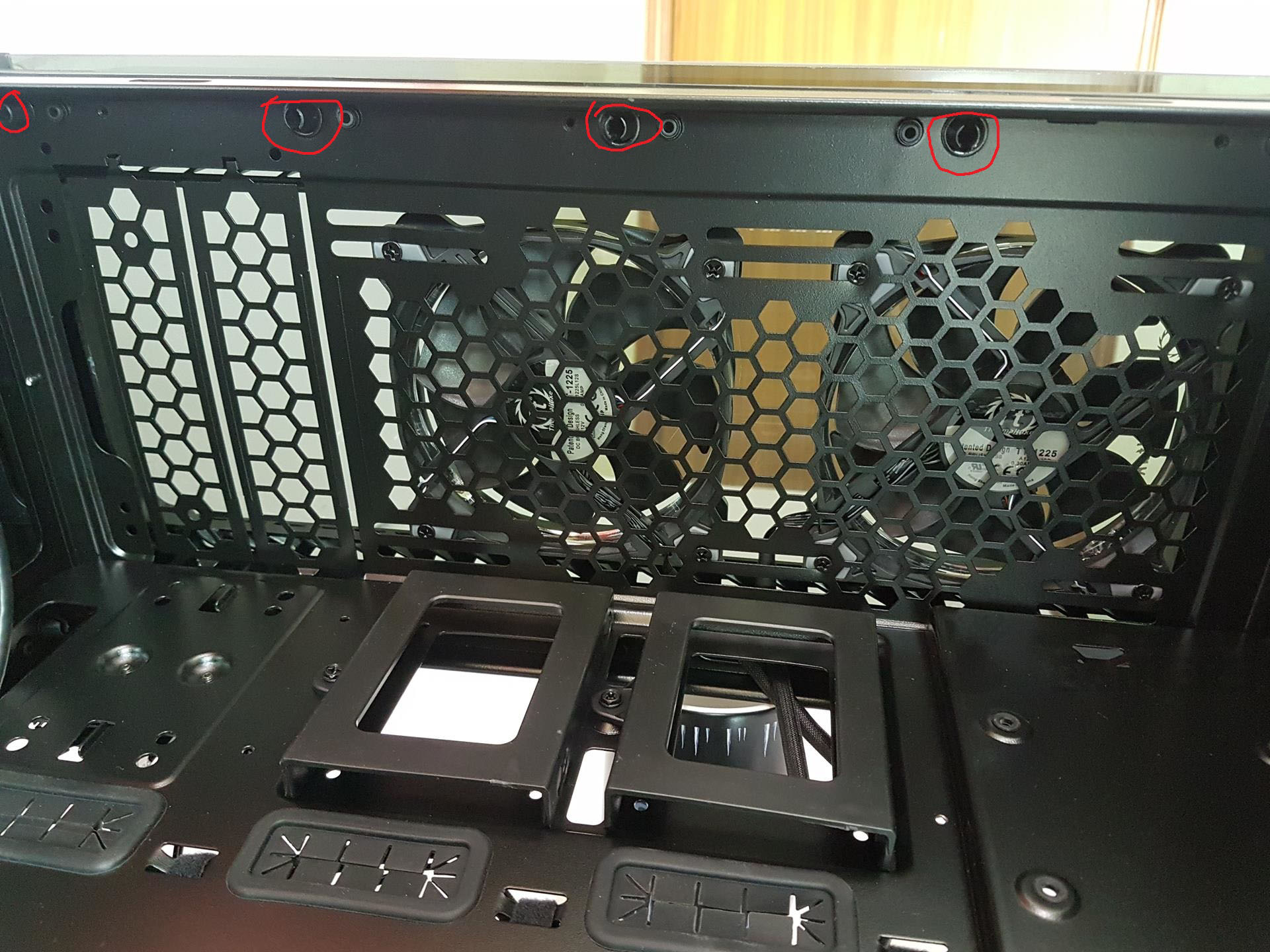
Now, that we have discussed the inside of the chassis, it is time to take a look at the rear side and underside of it. On the top of the rear side, there are angular vents with a height of less than 20mm. Below them, we have a cutout for the motherboard’s I/O shield. On its right side, we have a mounting provision for a 120mm fan with up to 4 height-adjustable fan mounts.
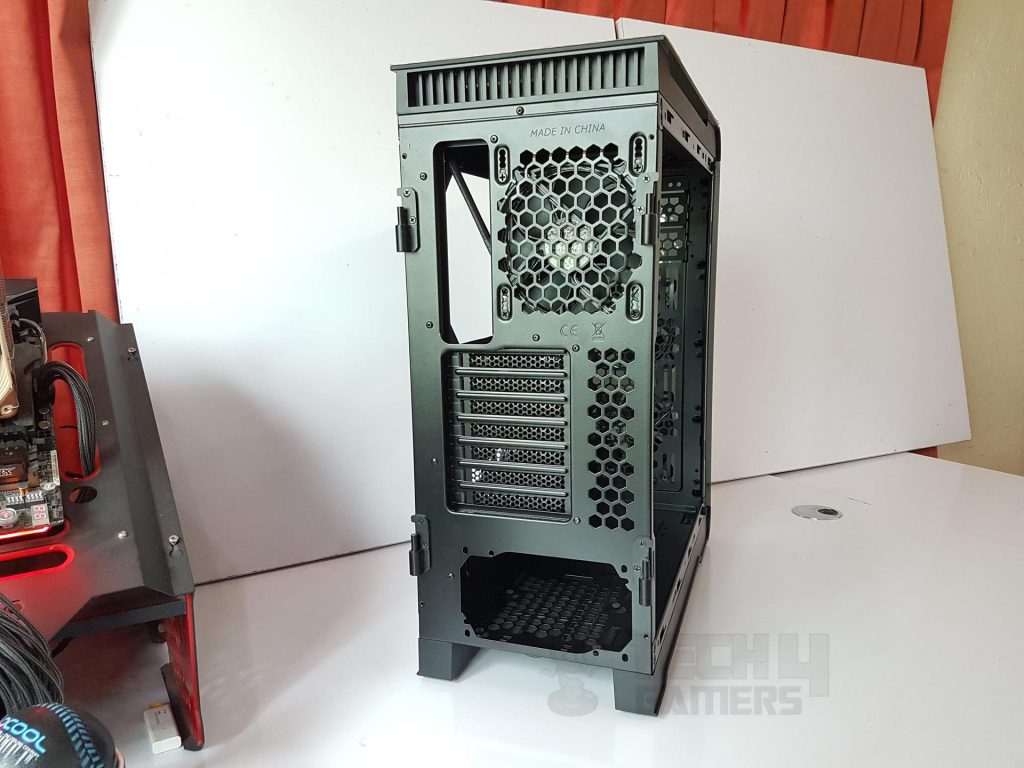
Below that we have 7 PCIe slot covers with mesh design and there is a large size meshed cutout design on their right side for air ventilation. At the bottom, there is a standard ATX-size PSU mounting location.
Bottom
The underside area of the chassis has a non-magnetic dust filter beneath the PSU area. Rest is a solid surface.
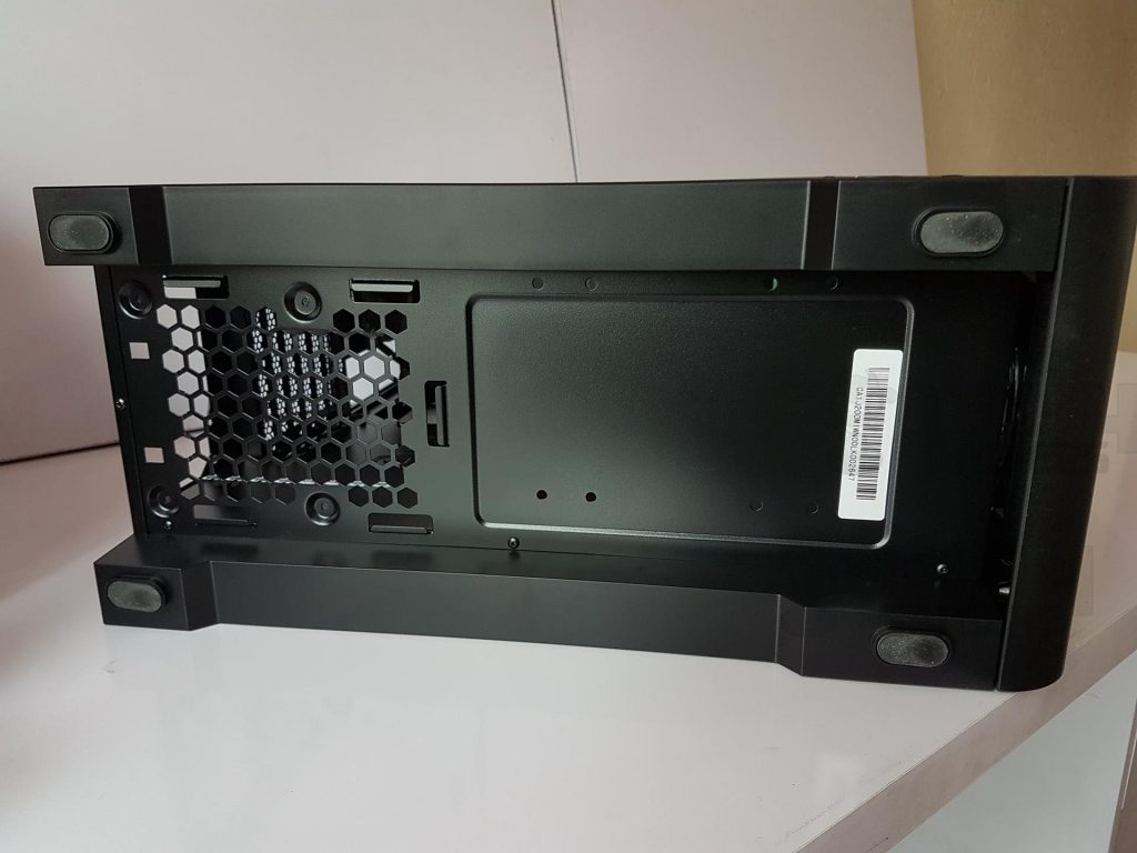
The main frame is inset on the border and there is a 46mm gap between the inset area to the surface where the chassis will be placed making it a good enough clearance for PSU to draw fresh air or exhaust the hot air. The four feet have rubber inserts to avoid scratching the surface on which the chassis will be placed. Also, there is a gap between the angular rounded bottom part of the chassis and the bottom sheet. I am not sure if it is for intake or what.
Backside
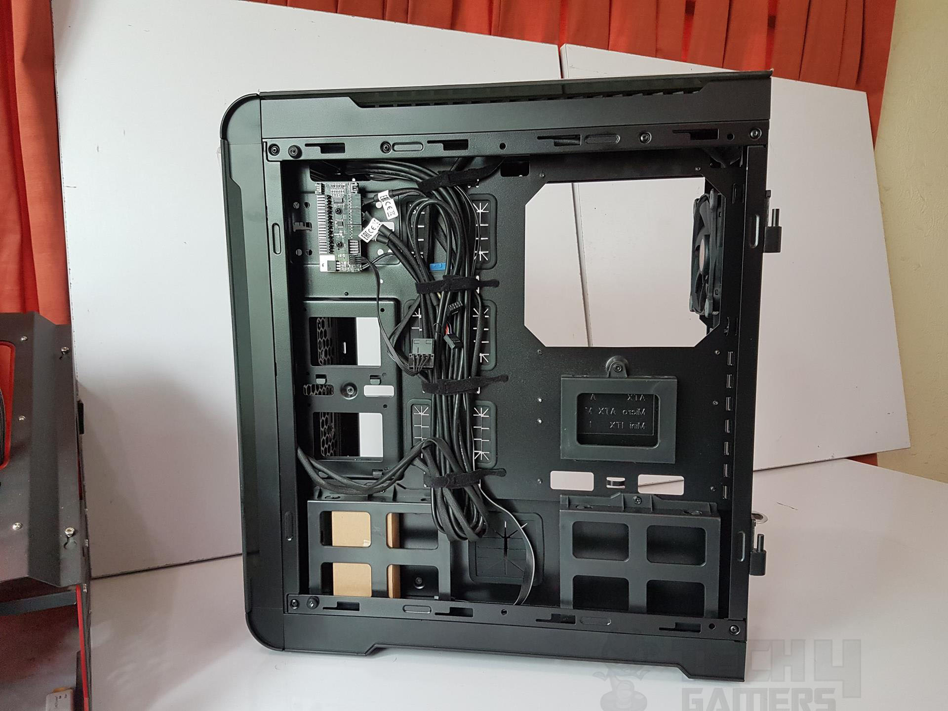
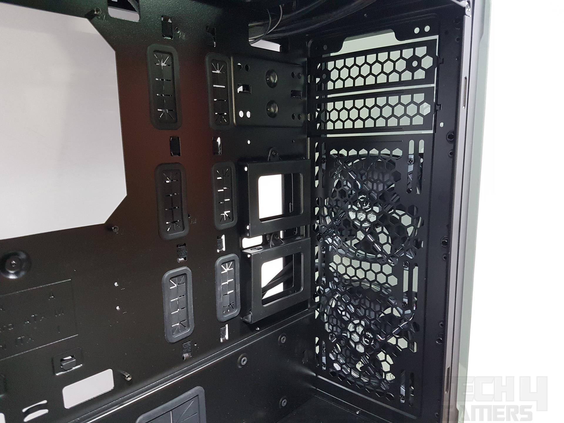
Let’s take a look at the backside of the motherboard tray. One instant pick would be the lack of cable tie hooks on this side. This could be due to the fact that there are three caddies in addition to the Controller Hub that is taking up a lot of space on this side.

But the good thing is that Thermaltake has provided 4 large-size adjustable Velcro Cable ties on the top and bottom of the main cutouts with rubber grommets.

The small-size caddy below the CPU cutout tray is for the 2.5” SSD. There are two 3.5” HDD caddies as well on the bottom side facing each other. There is a 38mm of spacing or clearance for the cable management without these caddies and with these caddies, this space is 25mm which is plentiful.
Clearly, Thermaltake was considerate to make up for the covered space. We will discuss the controller hub in the RGB LED lighting section ahead. In my opinion, the cable dots should have been included particularly above the CPU cutout tray and below it.

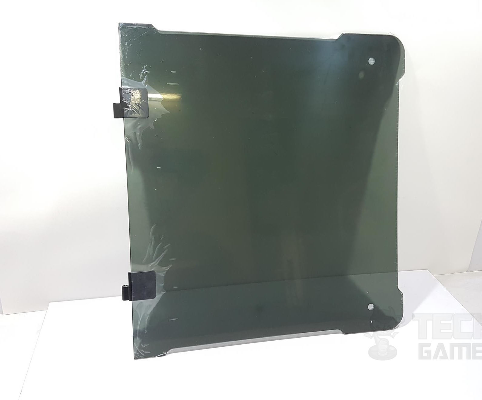
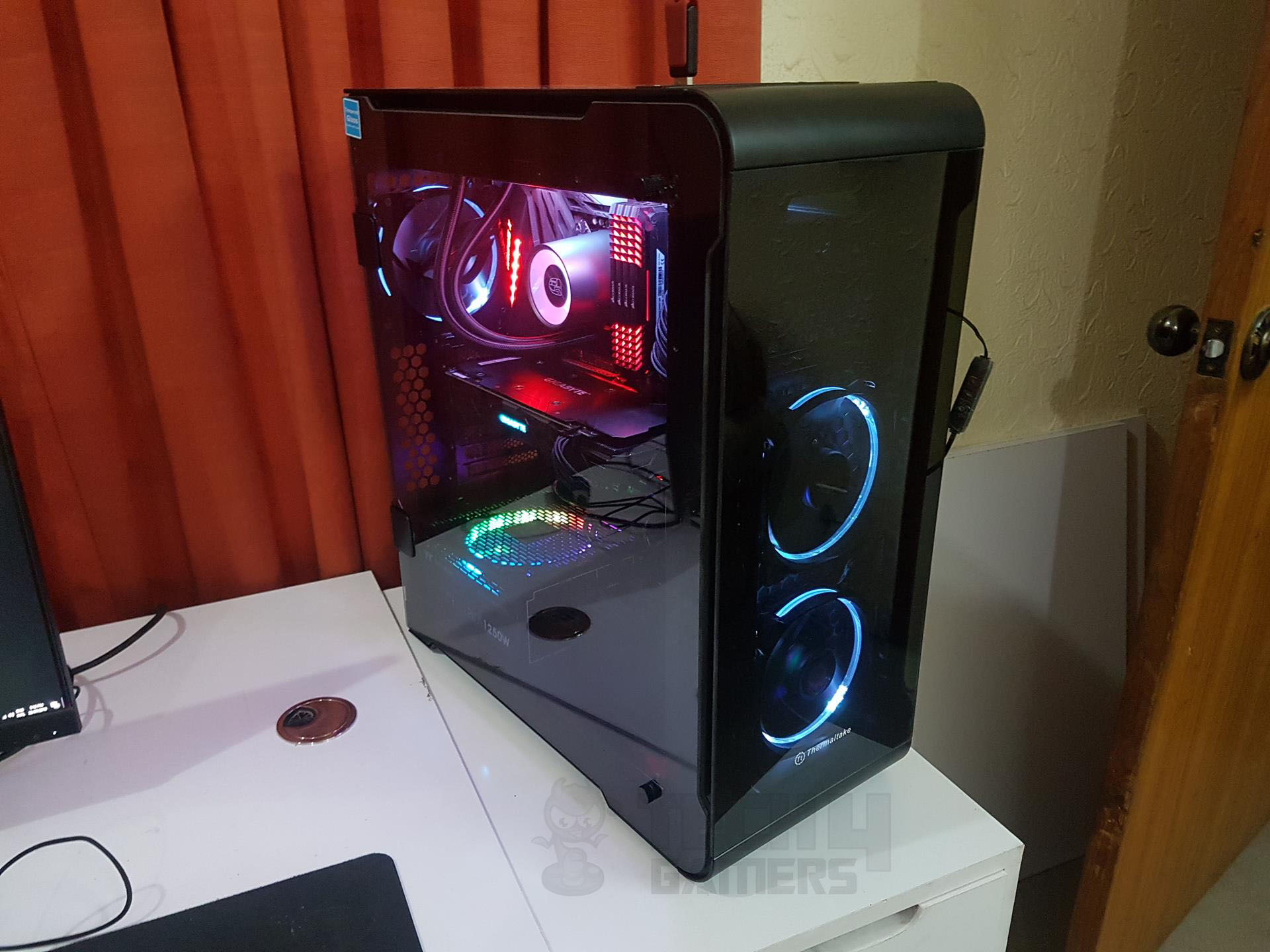
The good thing about the side panels is that they are hinged implemented which is a plus. No longer one is concerned about holding the panel onto the chassis frame by aligning the mounting holes on the panels to the chassis frame and similarly no risk of accidentally breaking the panel when taking them off.
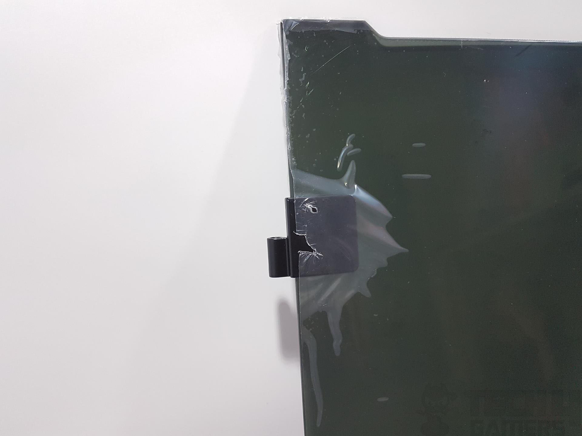
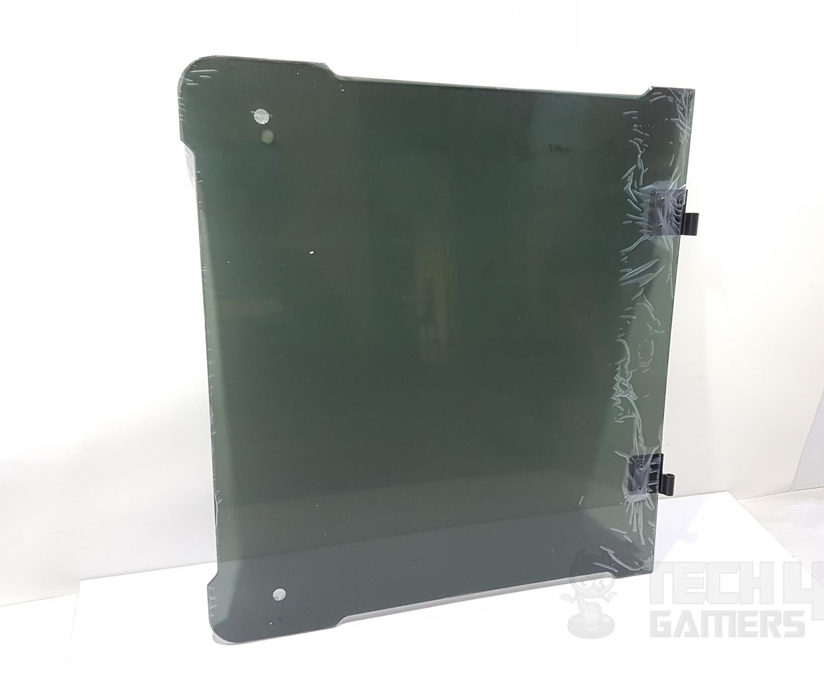
As they are hinged they will rotate freely and all the user would need to complete their installation is to secure them using the two thumb screws with a rubber insert. This is too good a detail to the attention. Mind you these panels are heavy and leaving one open at full swing could imbalance the chassis.
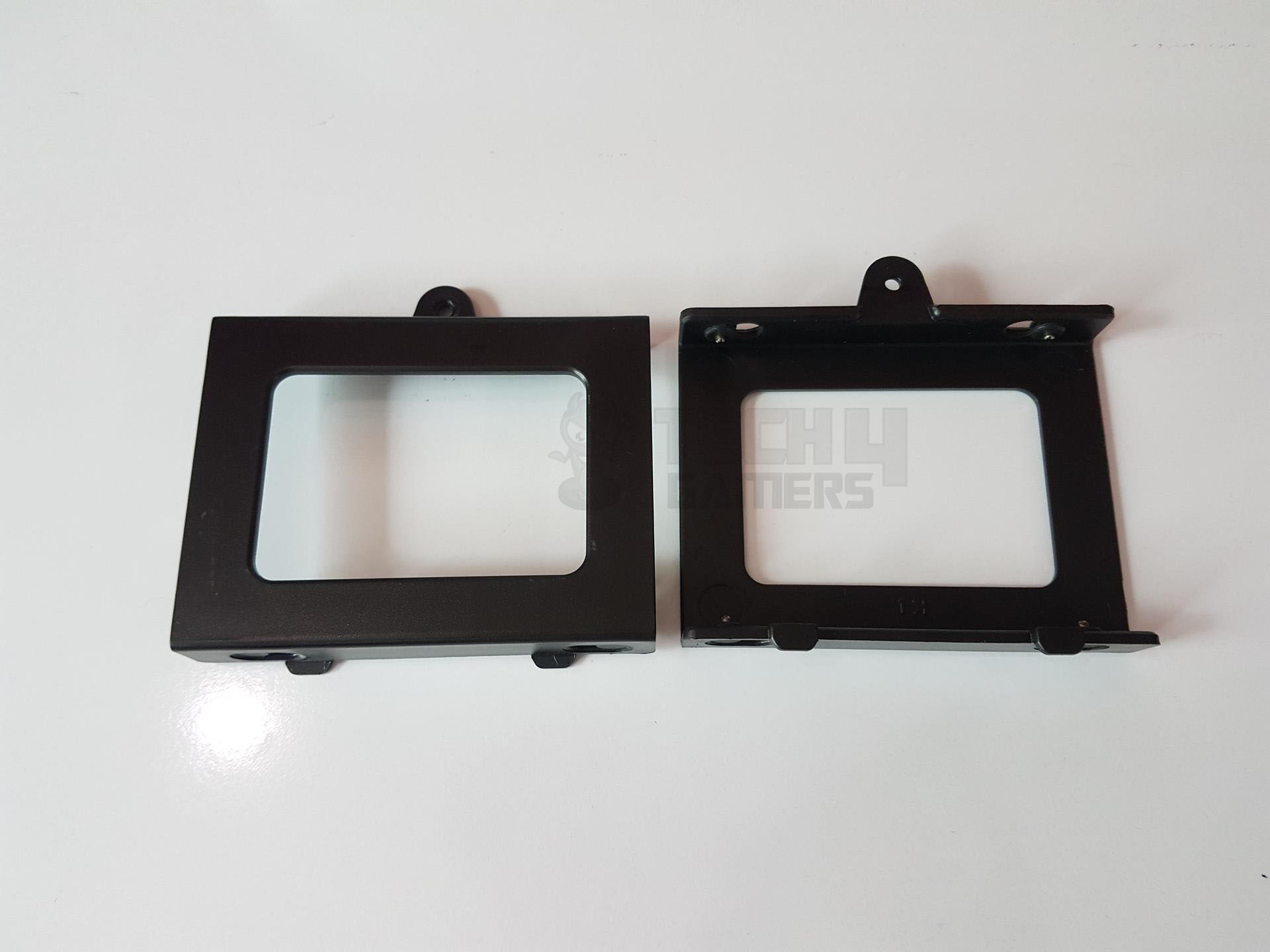
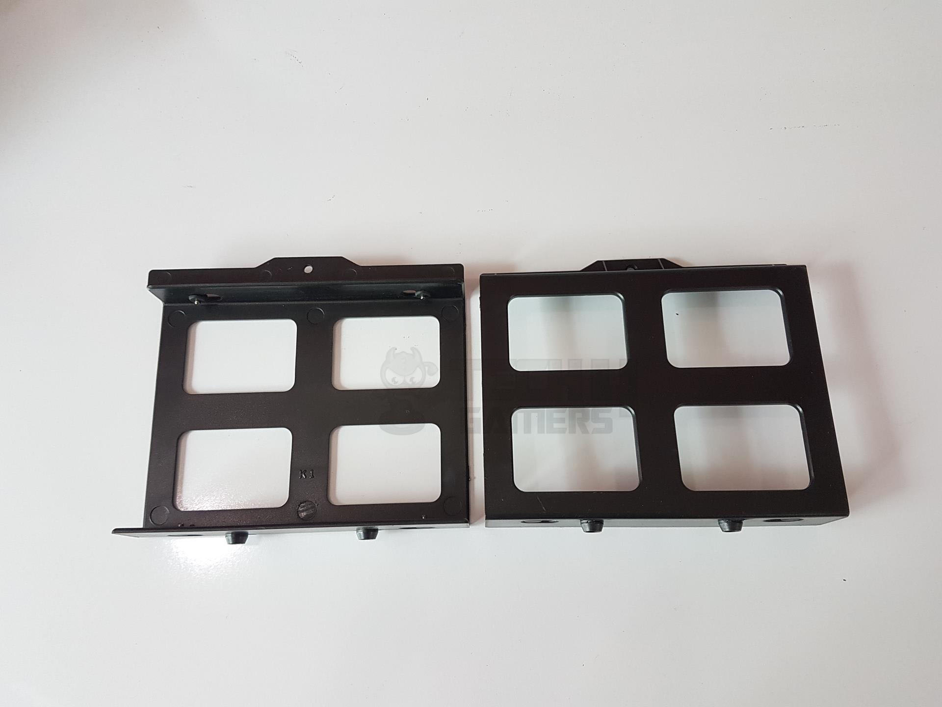
Though Thermaltake is calling it a tool-free installation of the storage drive(s), one would need to take the caddies off to install/un-install the drives for which a screwdriver is needed. Hence, while it may be tool-free mounting onto the caddies this is not tool-free for the caddies’ installation. This could have been tool-free if thumb screws were provided.
Here are the cooling hardware support pictures for ready reference.

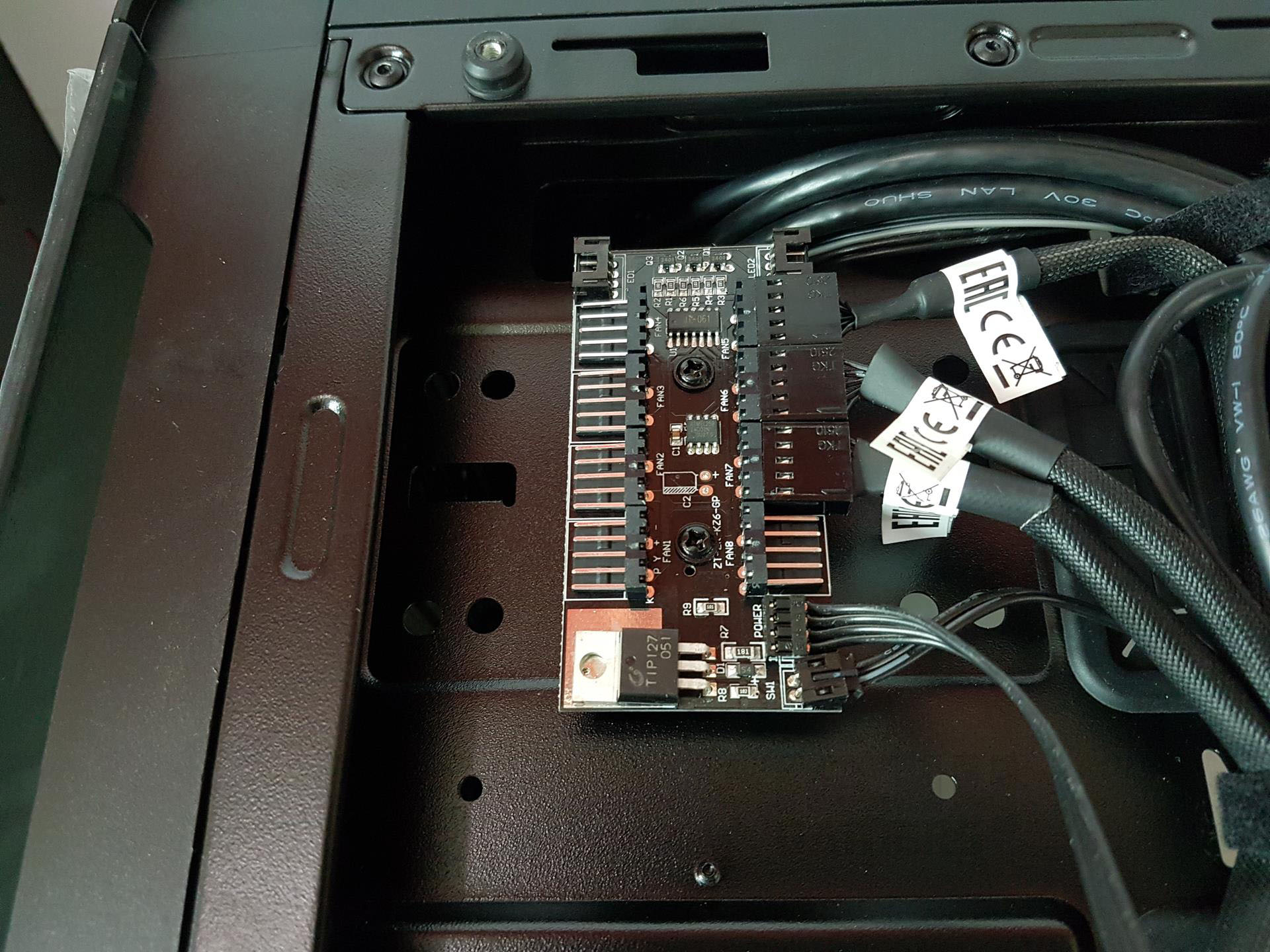
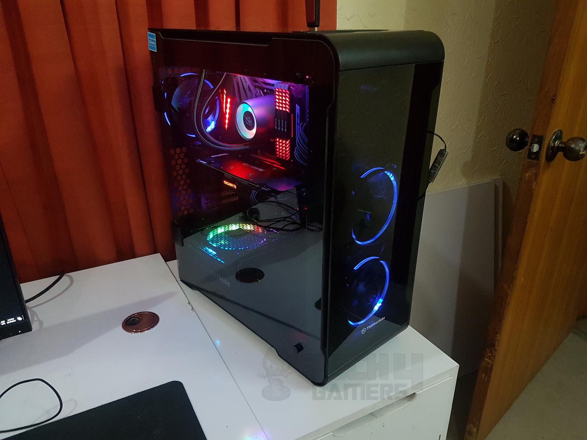
RGB LED Lighting
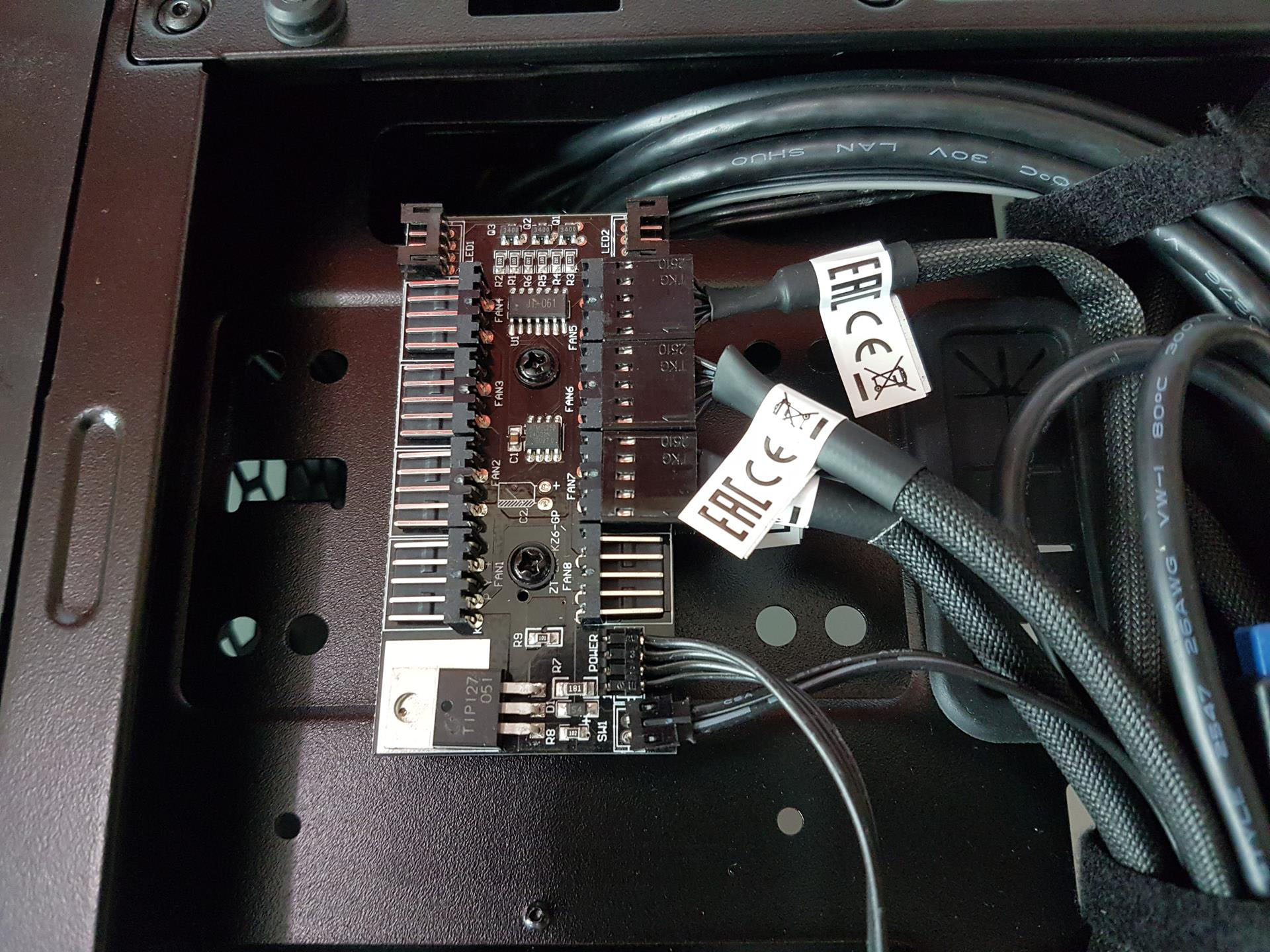
The chassis features three Riing RGB fans with 256 basic colors. A control button on the top I/O panel manages lighting effects, while the controller hub, supporting two LED strips and up to 8 RGB fans, is at the back. The RGB button allows for turning off or on the lighting. The fans run at 1400 RPM and produce 28dB(A) noise. Six lighting modes are available.
Note that the 5-pin proprietary connector limits speed control. The included hub is compatible only with the Thermaltake Riing 12 LED RGB Fan Series.

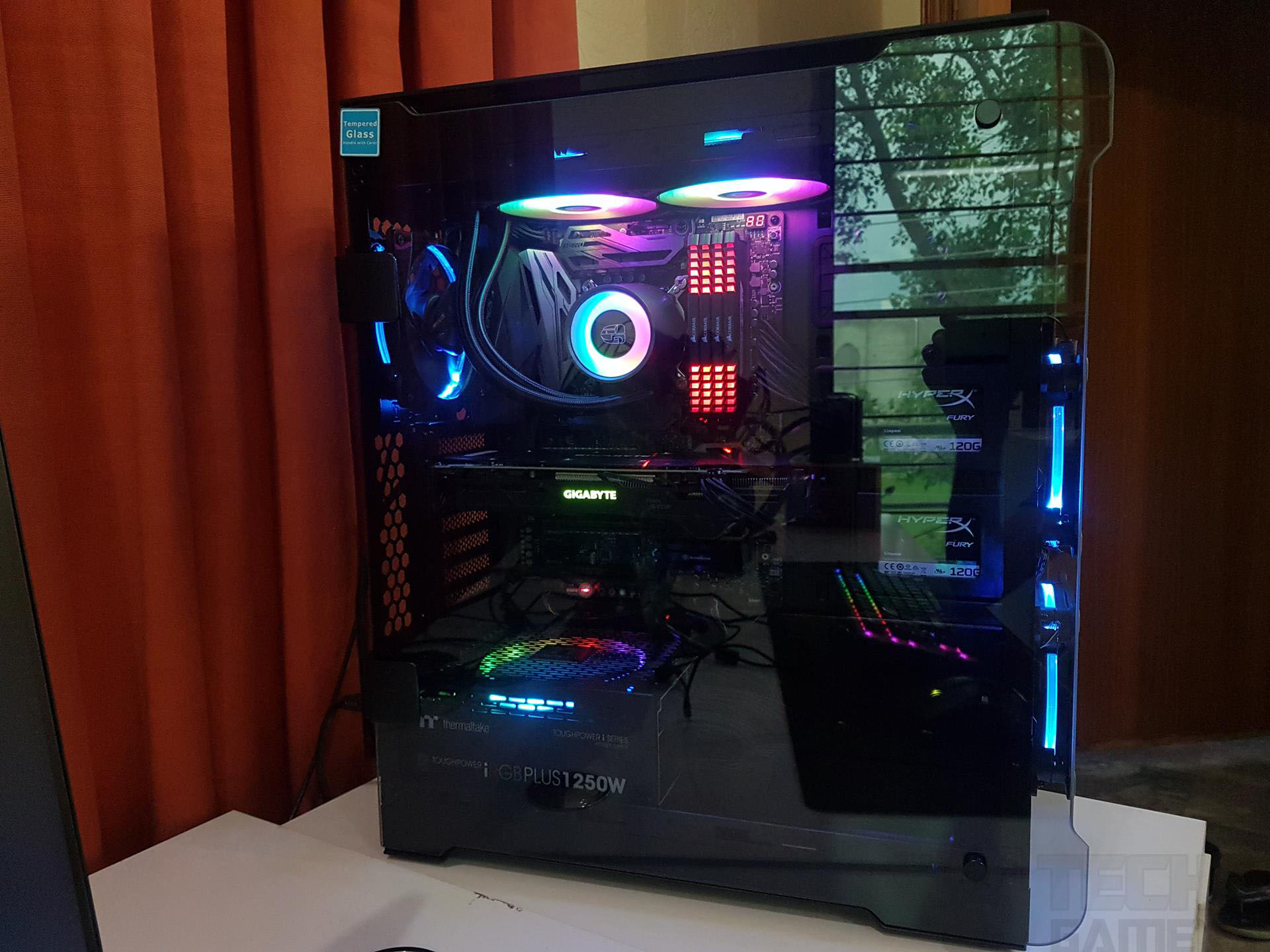


Building/Installation
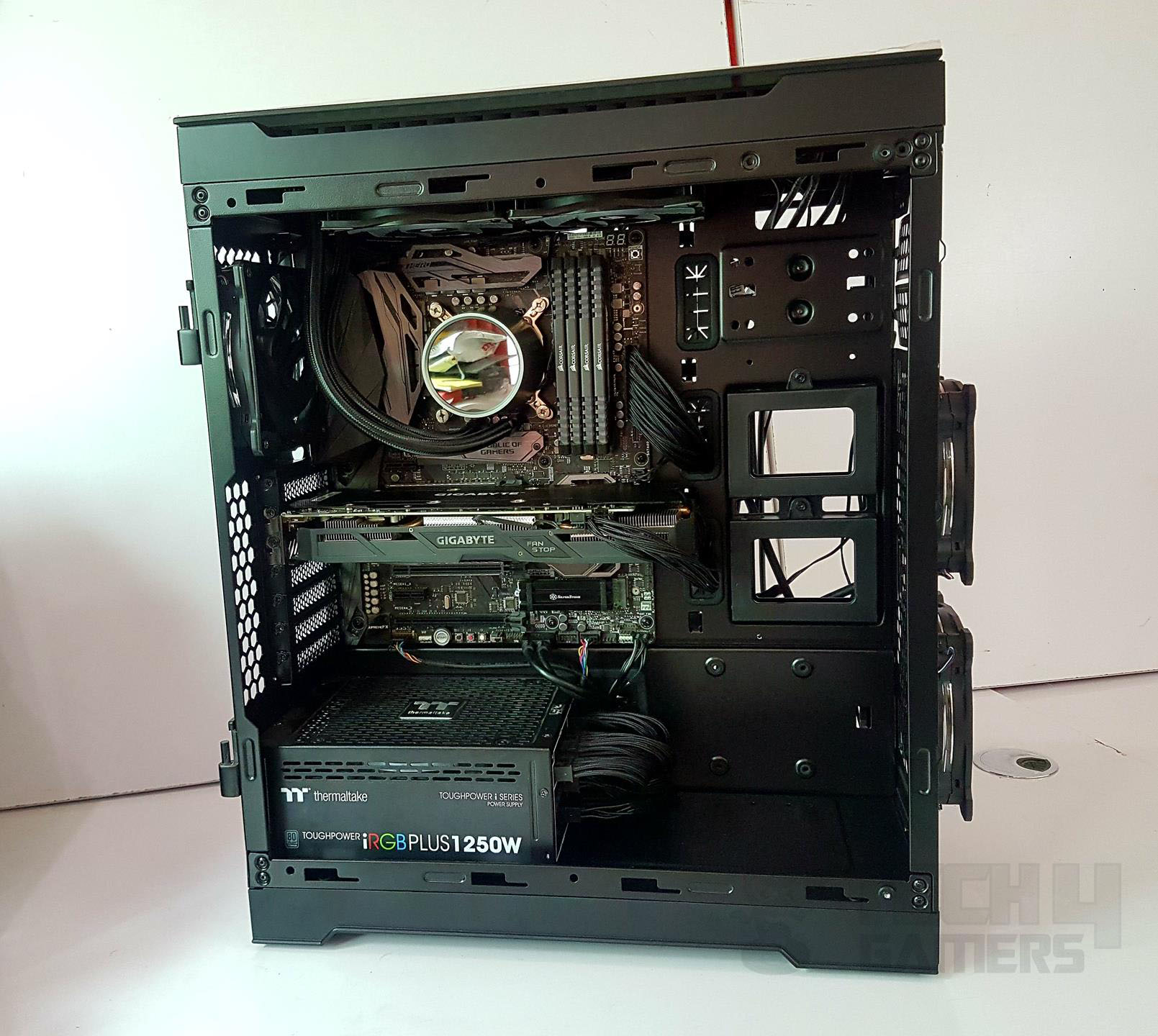
Following is the configuration of the test build:
- Intel i7 8700k
- Deepcool Castle 240 RGB Liquid cooler
- Corsair Vengeance Red 4x8GB @ 2666MHz
- Gigabyte GTX 1060 6GB Gaming G1
- Samsung 256GB PM961 SSD
- Samsung 840 1TB SSD
- WD 6TB Black
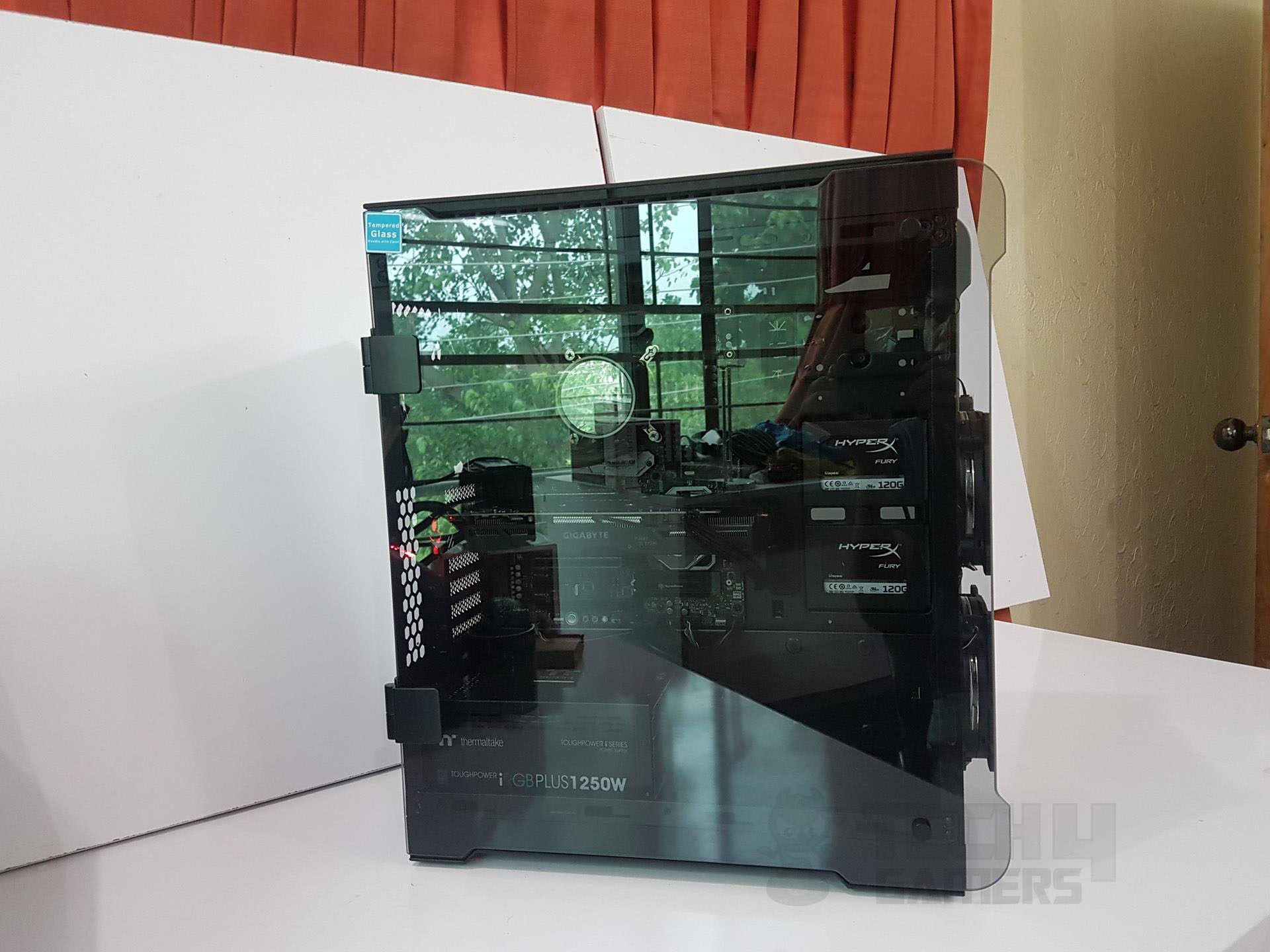
- Thermaltake ToughPower iRGB Plus 1250 PSU
I could not use the Nvidia GTX 1080 FE as it is water-cooled using the Alphacool Eiswolf GPX Pro cooler and is being used on the test bench.
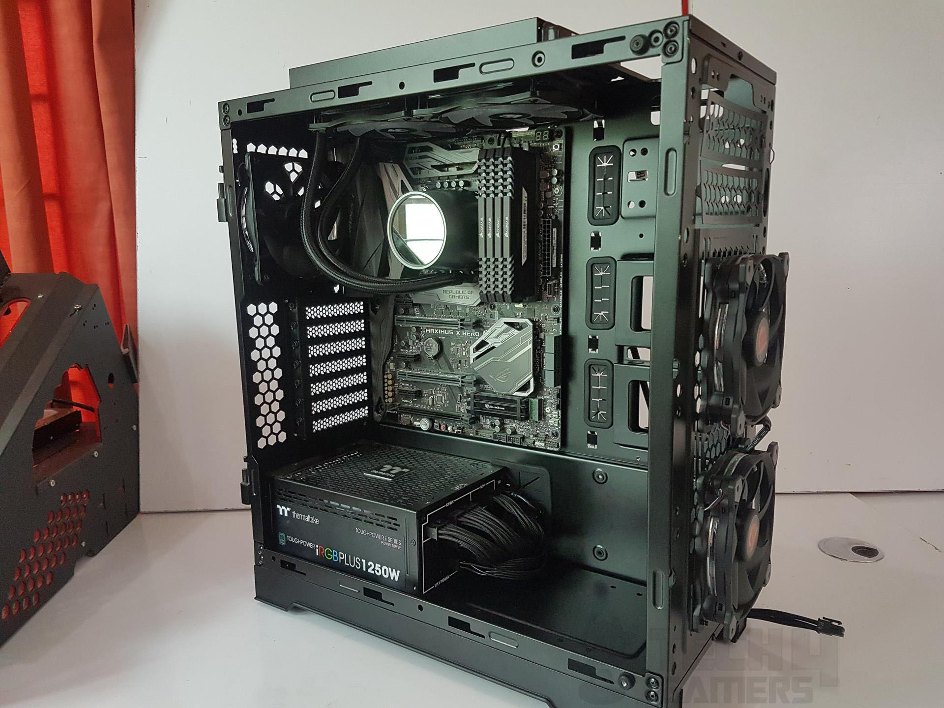
Building inside the chassis was enjoyable, thanks to its spacious layout. I began with the motherboard, noting that installing high-profile RAM is easier after the cooler installation. The PSU came next, and passing cables through the large cutout at the bottom caused a minor issue with the rubber grommet. For full ATX motherboards, cable routing is limited to the third cutout on the right, making cables partially visible. Use flat cables cautiously to route them before motherboard installation. Note the risk of potential damage during this process.
If you are using high-profile RAM, better keep them to keep it installed after the installation of the cooler. mTake your time for the cable management on the back. As the side panels are dark-tinted, cables won’t be visible unless you put some LED strip on the backside.

Testing
It is summer time here and there are certain noises that are beyond our control hence we did not measure the acoustics of the completely assembled PC. But based on our testing, the overall noise level was adequate and not teasing. Our i7 8700k is a damn hot chip that has left us with no choice except not going for the thermal testing.
We will soon be delivering this chip for the proper thermal testing purpose. On stock clocks with turbo boost, the chip did a maximum of 72°C while gaming Battlefield 1 at 4k with Ultra settings whereas the Graphics card did a maximum of 73°C max.
Should You Buy It?
After testing, I was able to determine who the case was designed for.
Buy It If:
✅ You want a spacious case with effective airflow: The Thermaltake View 32 offers a roomy interior and thoughtful ventilation design.
✅You preferred tempered glass panels: The Thermaltake View 32 comes with four separate tempered glass side panels that accentuate the case’s visual appearance.
✅You are a fan of RGB lighting: RGB lighting is present on the Thermaltake View 32 along with a controller.
Don’t Buy It If:
❌You are working with a smaller budget: While the Thermaltake View 32 is not priced aggressively, it is likely not an ideal purchase for anyone who wants to build a budget PC.
❌You want a dedicated PSU cover: The Thermaltake View 32 does not come with a separate PSU cover.
Conclusion
The Thermaltake View 32 is a mid-tower chassis that has a beautiful design merged with four 4mm tempered glass panels (Top, Front, Left, and Right) and 3 LED Riing RGB fans. This is a little brethren of the full tower View 71. The dimension of the chassis is 480 x 227 x 524 mm. This chassis is Tt LCS certified.
The chassis provides good clearance for components, with a well-thought-out spacing design. The hinged installation mechanism of the side panels enhances ease and safety during handling. Cable management is aided by adjustable Velcro strips, and the controller hub supports RGB customization for up to 8 fans and 2 LED RGB strips. However, the proprietary 5-pin connectors limit user control over fan speed.
Installation is straightforward, but removing the top panel can be challenging and requires careful handling. The RGB fans offer six lighting modes, enhancing aesthetic appeal. Despite minor shortcomings, the Thermaltake View 32 provides a spacious and stylish platform for building and testing a PC, ultimately delivering a satisfying experience for enthusiasts.
Recent Updates
- December 26, 2023: Few text changes to improve readability. No products were changed.
Thank you! Please share your positive feedback. 🔋
How could we improve this post? Please Help us. 😔
[Hardware Reviewer & Editor]
Meet Nauman Siddique, a highly experienced computer science graduate with more than 15 years of knowledge in technology. Nauman is an expert in the field known for his deep understanding of computer hardware.
As a tech tester, insightful reviewer, and skilled hardware editor, Nauman carefully breaks down important parts like motherboards, graphics cards, processors, PC cases, CPU coolers, and more.
- 15+ years of PC Building Experience
- 10+ years of first-hand knowledge of technology
- 7+ years of doing in-depth testing of PC Hardware
- A motivated individual with a keen interest in tech testing from multiple angles.
- I majored in Computer Science with a Masters in Marketing
- Previously worked at eXputer, EnosTech, and Appuals.
- Completed Course in Computer Systems Specialization From Illinois Tech
Get In Touch: nauman@tech4gamers.com