 Threads
GIGABYTE Z790 AORUS ELITE AX Motherboard
Review Summary
The GIGABYTE Z790 AORUS ELITE AX is a well-balanced motherboard with a feature set that would easily provide the daily-driver requirement in the main-stream mid-range market segment. If GIGABYTE does the right pricing, this could be easy picking for this segment. The only caveat is the lack of a Gen 5-based M.2 port.
Hours Tested: 17

Overall
-
Performance - 8/10
8/10
-
Features - 8/10
8/10
-
Value - 9/10
9/10
-
Design - 8/10
8/10
Pros
- 16+1+2 Power Phases
- Effective VRM/MOSFET Cooling
- 1x PCIe Gen5 x16 slot
- 2x PCIe Gen4x4 slots
- EZ-Latch on PCIe Slot
- 4x M.2 Gen4x4 NVMe ports
- EZ-Latch on M.2 Ports
- Good enough USB ports
- 1x USB Type-C Gen 2×2 port
- Quick Flash Plus Button
- Subtle RGB Lighting under the Chipset Cover
- Wi-Fi 6E
- 5 GbE LAN Connectivity
- 3 Bluetooth
- Clear CMOS Button
- Overall good performance
Cons
- One M.2 port shares the bus with 2x SATA ports
- No External Temperature Sensor Ports
- No Debug LED


While the tech testers were busy in testing the AMD Zen 4 platform, Intel has released their 13th gen platform named Raptor Lake. They have introduced new chipsets for this generation; peculiar of which is Z790. This generation of the Core processors use the same LGA1700 socket hence we have compatibility of 12th gen Core i processors on the 13th gen and vice versa. We are taking a look at the mid-range segment motherboard from GIGABYTE in Z790 chipset series which is GIGABYTE Z790 AORUS ALITE AX.
Key Takeaways
- The GIGABYTE Z790 AORUS ELITE AX is a mid-range, feature-rich ATX motherboard for Intel’s 12th/13th/14th gen processors, offering robust power delivery, extensive connectivity options, and advanced cooling solutions with support for DDR5 memory and Wi-Fi 6E.
- You should buy the GIGABYTE Z790 AORUS ELITE AX if you want solid value, an overall balanced set of features, good performance, and RGB lighting.
- You should skip the GIGABYTE Z790 AORUS ELITE AX if you plan on using a Gen5 SSD or if the lack of a debug LED is a dealbreaker for you.
Let’s start with the salient features of the motherboard:
- Intel® Socket LGA 1700:Support 13th and 12th Gen Series Processors
- Unparalleled Performance:Twin 16+1+2 Phases Digital VRM Solution
- Dual Channel DDR5:4*SMD DIMMs with XMP 3.0 Memory Module Support
- Next Generation Storage:3*PCIe4.0 x4 M.2 Connectors
- Advanced Thermal Design & M.2 Thermal Guard:To Ensure VRM Power Stability & M.2 SSD Performance
- EZ-Latch:PCIex16 Slot & M.2 Connectors with Quick Release & Screwless Design
- Fast Networks:2.5GbE LAN & Wi-Fi 6E 802.11ax
- Extended Connectivity:HDMI, DP, Rear USB-C® 20Gb/s, Front USB-C® 10Gb/s
- Smart Fan 6:Features Multiple Temperature Sensors, Hybrid Fan Headers with FAN STOP
- Q-Flash Plus:Update BIOS Without Installing the CPU, Memory and Graphics Card
The twin above means 6 parallel phases.
Last Updated:
- June 16 2024: We have changed the formatting to improve readability.
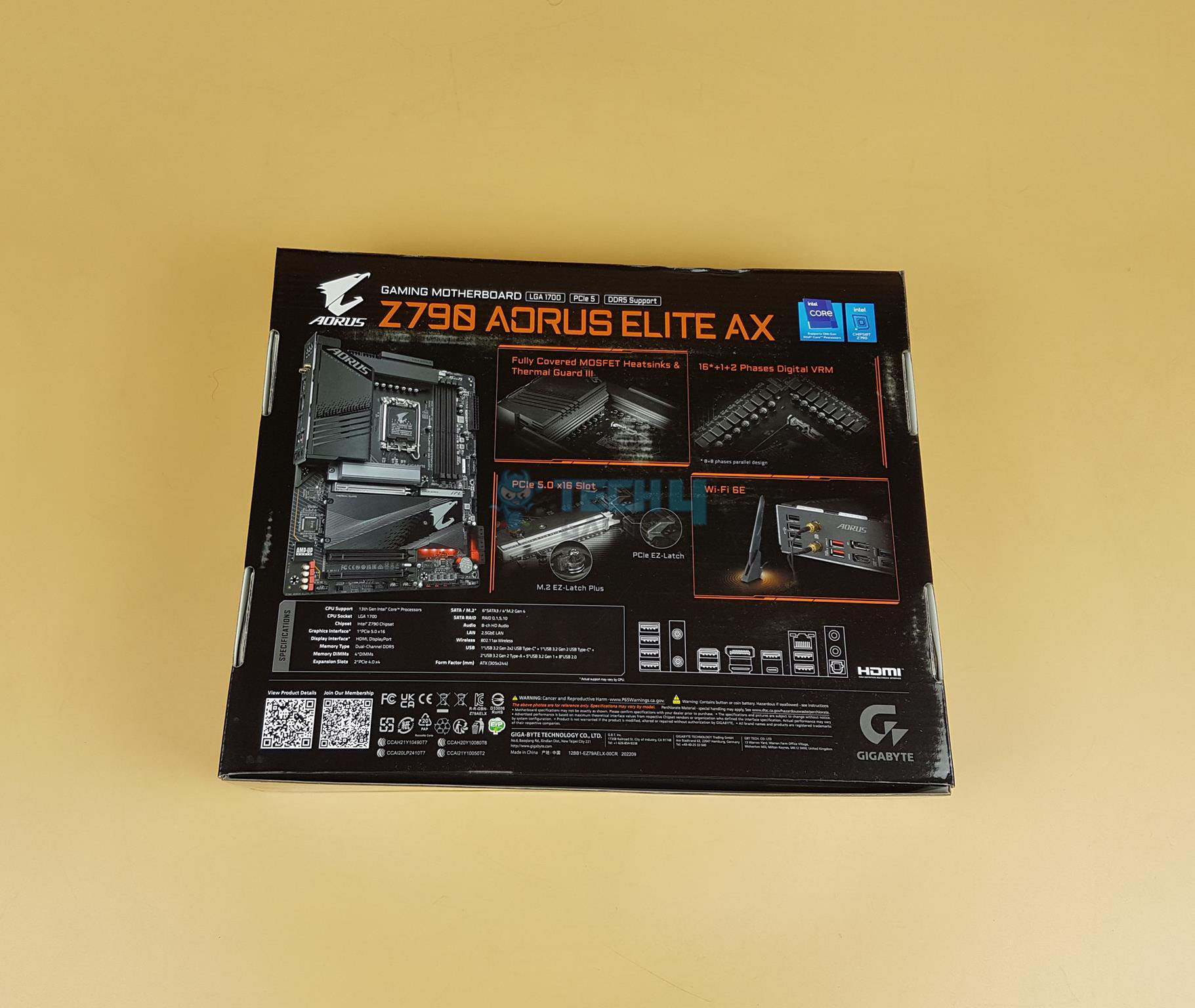
The key specifications are:
| CPU Support | Intel 14th, 13th & 12th Gen |
| Memory Support | 4x DIMM Slots for DDR5 up to 7600MHz+ (OC) |
| PCIe Slots |
|
| M.2 Ports | 4x M.2 Gen4 Ports (1x from CPU, 3x from chipset) |
| VRM | 6x |
| VRM | 16+1+2 |
| Network | 2.5GbE LAN, WiFi 6E, BT 5.3 |
| USB Ports | Total 17x USB Ports (Front and Rear), including 1x Type-C USB 3.2 Gen2x2 at the pack and one Type-C USB 3.2 Gen2 at the front |
| Size | ATX Form Factor; 30.5cm x 24.4cm |
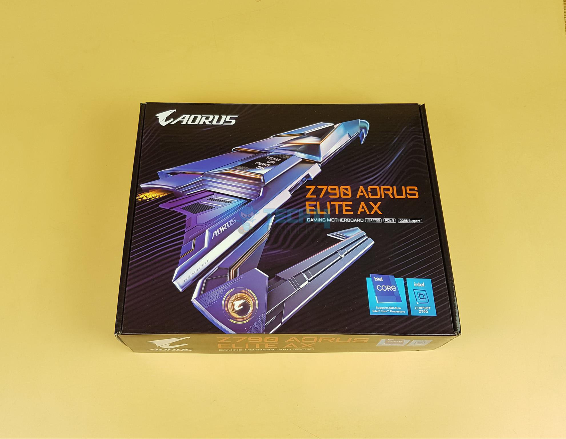
Packaging And Unboxing
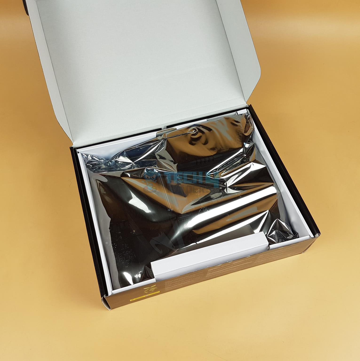
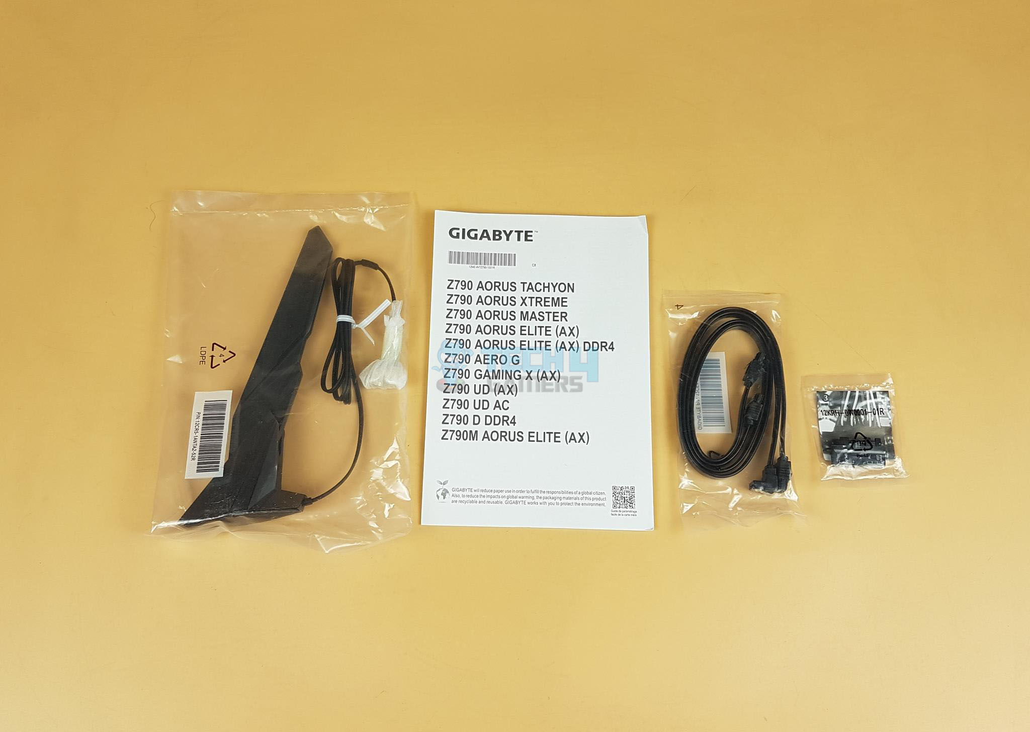
No user manual is provided in the box.
Closer Look
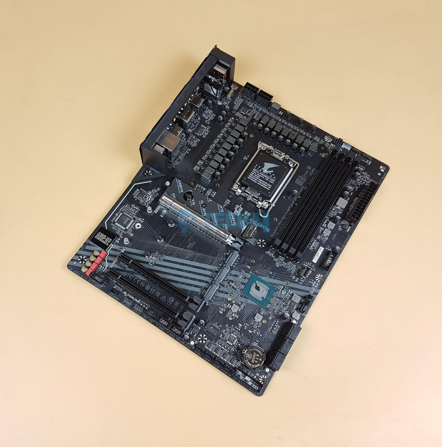
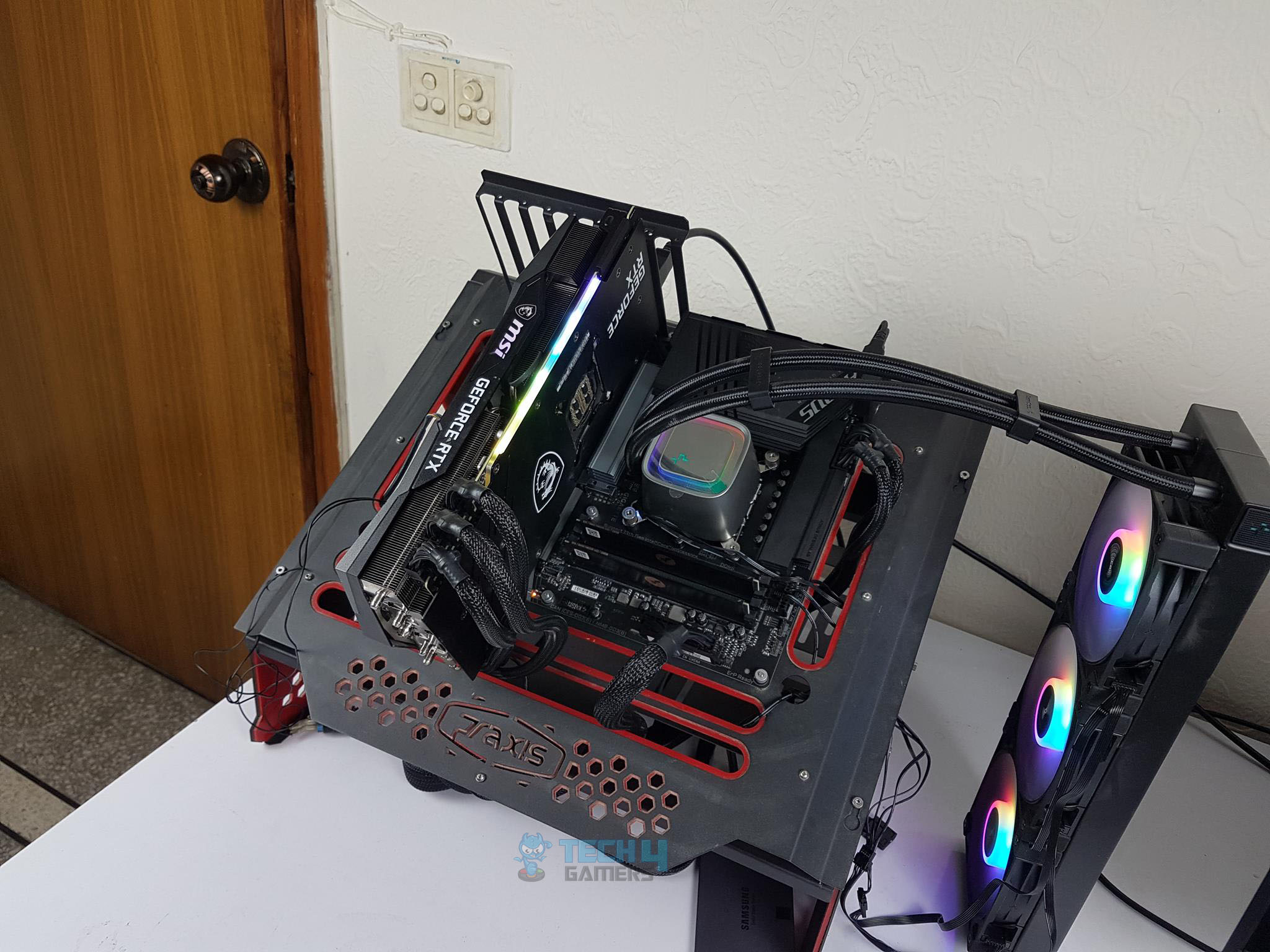
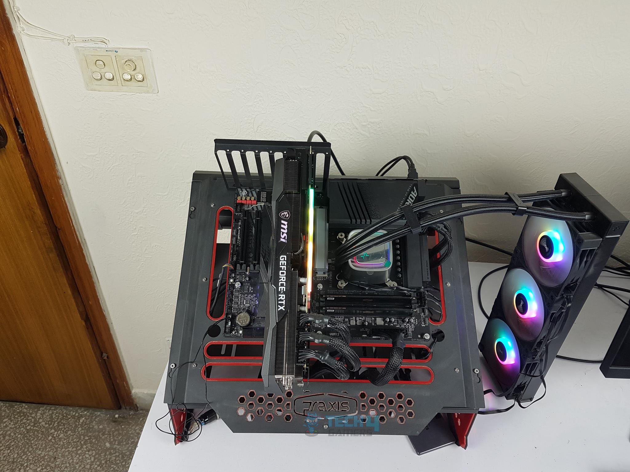
The Z790 AORUS ELITE AX motherboard is a mid-range segment motherboard from the GIGABYTE. The motherboard has a standard ATX size and is still feature-rich. We are seeing almost the same design and stenciling as we have seen on the B650 AORUS ELITE AX which we recently tested. GIGABYTE has done a fantastic job in the motherboard design department, delivering a solid product for enthusiasts. Let’s start exploring the motherboard.
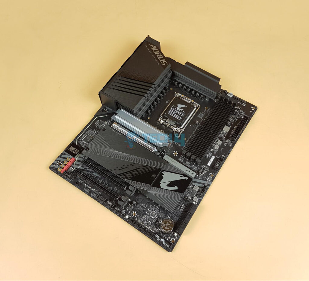
Taking a glance at the motherboard, we have a black color PCB. The heatsinks have black and gray color tone. The Chipset cover has RGB elements underneath. So, the RGB Fusion 2.0 is somewhat in play for the user on this motherboard because the lighting is not that elaborative. GIGABYTE has given due consideration to the cooling requirement of the key components all around. The chipset area is covered which in tandem with the M.2 ports cover, gives one stylish yet subtle outlook.
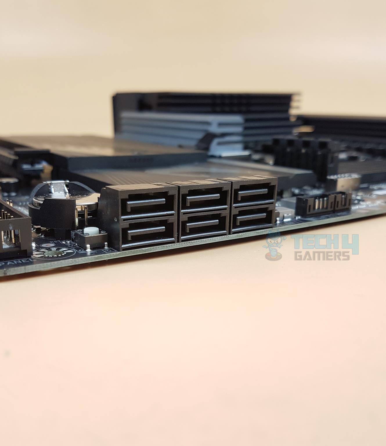
We have the same LGA1700 socket, 4x DIMM slots for DDR5 RAM, 3x PCIe slots at X16/X4/X4, 4x SATA ports, a plethora of USB ports, on-board audio solution driven by Realtek Amp-Up Audio, RealTek 2.5 GbE NIC, on-board WiFi 6E and nice handy I/O connectivity options. The 6-layered and 2x Copper PCB has a standard ATX form factor measuring 30.5cmX24.4cm and has support for Microsoft Windows 10 and 11.
CPU Socket, Heatsink, VRM, and Power Delivery
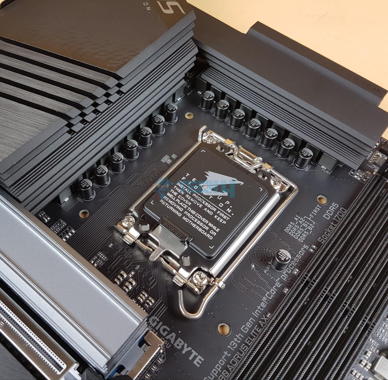
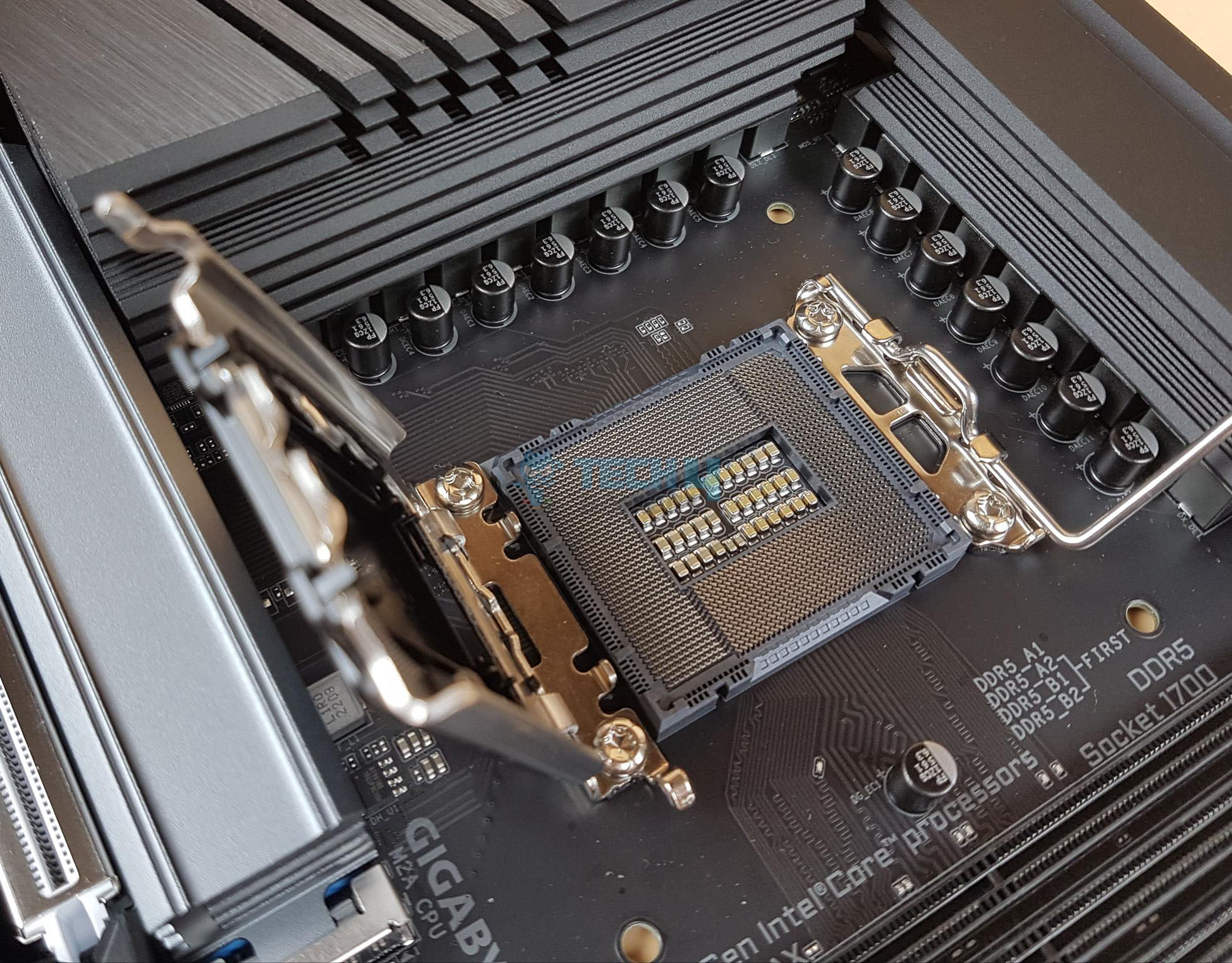
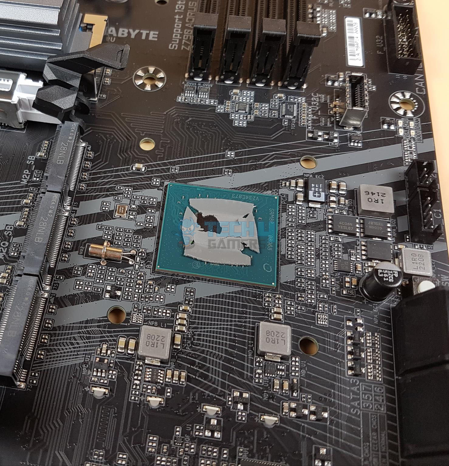
The Z790 AORUS ELITE AX features the same LGA1700 socket as we have seen on the Intel 12th generation platform. This gives cross-generation compatibility between the 12th and 13th generations from Intel. This also means that the underlying ILM design issue on the 12th gen sticks with the 13th gen. There is a protective cover over the socket area.
The above picture shows the socket after removing the protective cover. All the coolers compatible with the Intel LGA1700 will work with the 13th generation as well.
- Integrated Graphics Processor-Intel® HD Graphics support:
- 1 x HDMI port, supporting a maximum resolution of 4096×2160@60 Hz Support for HDMI 2.0 version and HDCP 2.3.
- 1 x DisplayPort, supporting a maximum resolution of 4096×2304@60 Support for DisplayPort 1.2 version and HDCP 2.3
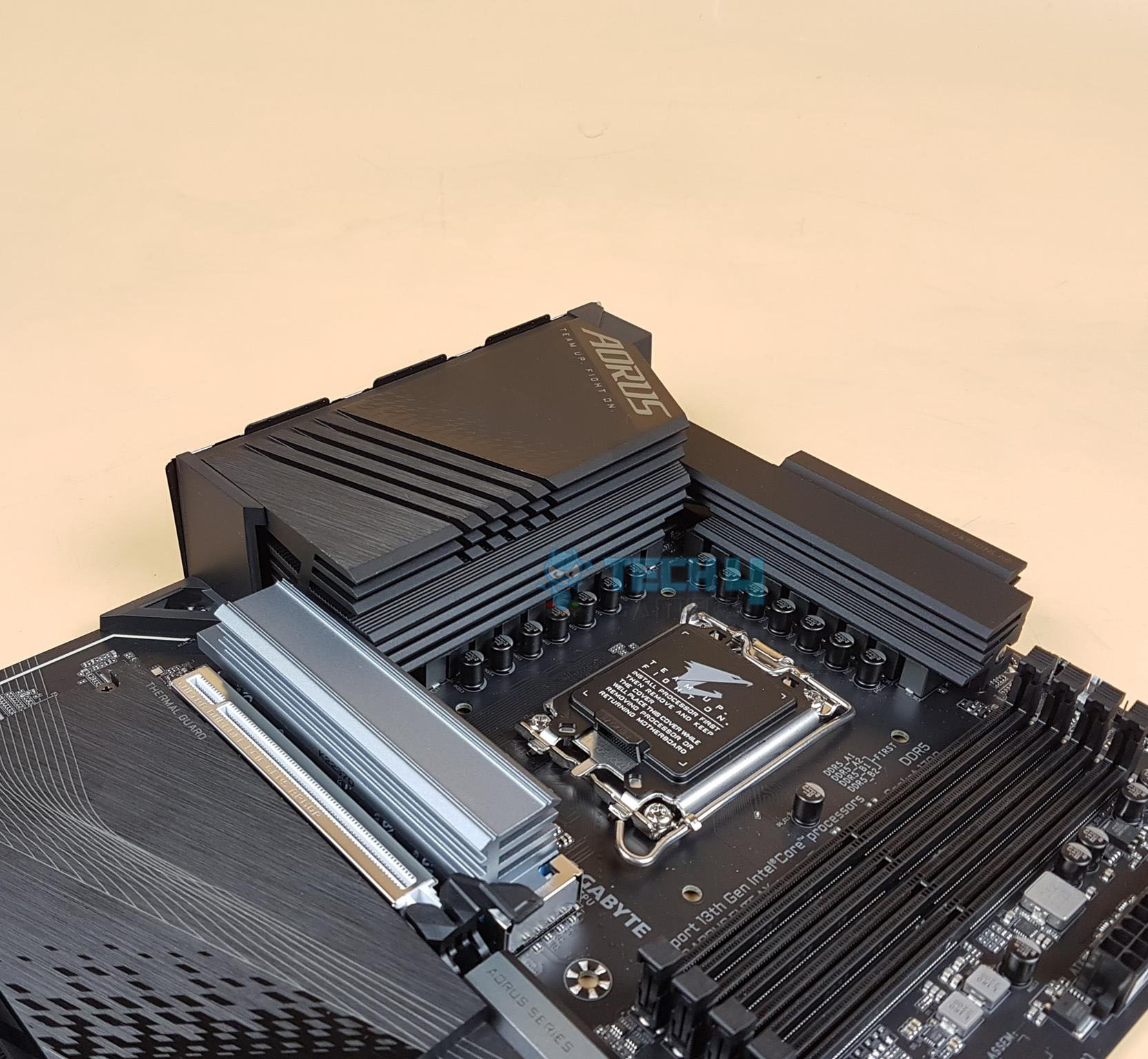
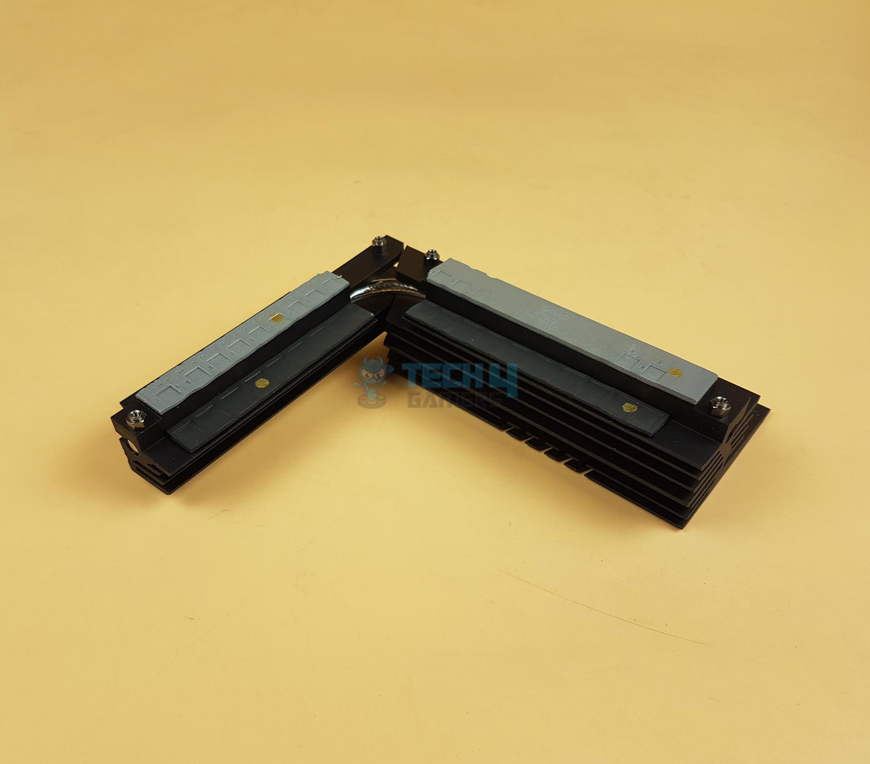
From a cooling perspective, GIGABYTE has implemented an effective solution. There is a massive heatsink covering the power delivery circuit. The cover has integrated molding heatsinks to improve heat transfer with better airflow.
Both heatsinks are connected using a 6mm thick copper heat pipe. The thermal pads are rated for up to 7.5W/mK. The salient features are:
- Increased surface area up to 4X larger compared to traditional heatsinks. It improves heat dissipation from the MOSFETs.
- TMOS is a TRUE single piece heatsink. Its one-piece design and larger surface drastically improve the cooling performance against competitors’ multi-piece design.
- TMOS features several channels and inlets on the heatsink. This design allows for the air flow to go through which leads to a great improvement of the heat transfer performance.
Since we are at it, let’s take a look at the power delivery of the motherboard.

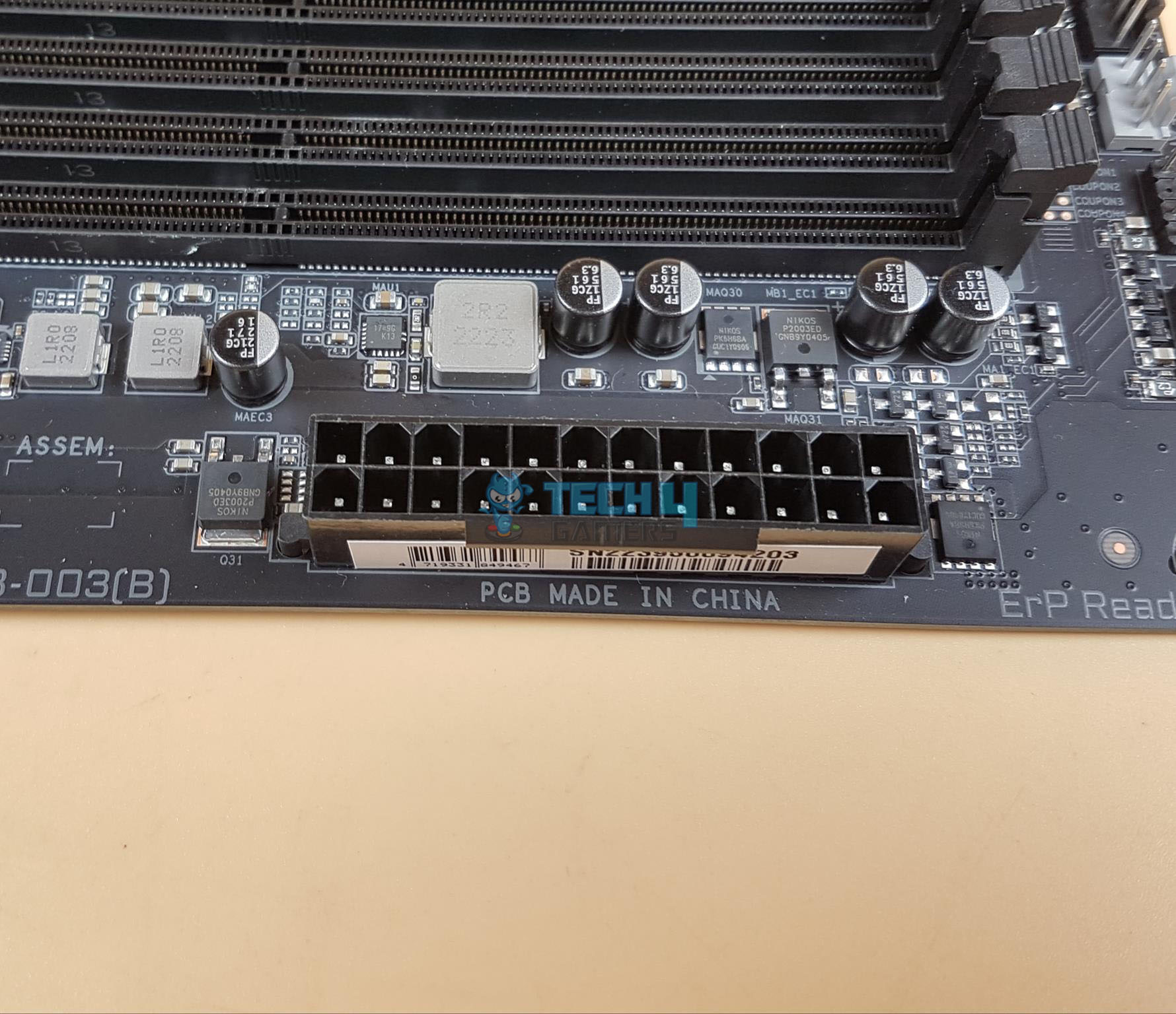
The Z790 AORUS ELITE AX motherboard has adequate digital power phases. There are 16 phases in parallel (not direct) for the VCore using Infineon TDA21472 SPS 70A making it 1120A. Then there is a MOSFET for GT using 5×5 footprint 60A for stable power delivery to the iGPU. Lastly, we have 2x MOSFETs for AUX using ON NCP303160 60A with a total of 120A for stable power delivery to the PCIe lanes. In terms of power delivery this motherboard seems adequate enough in this range though twin digital 16 phases sounds like a doubler design.
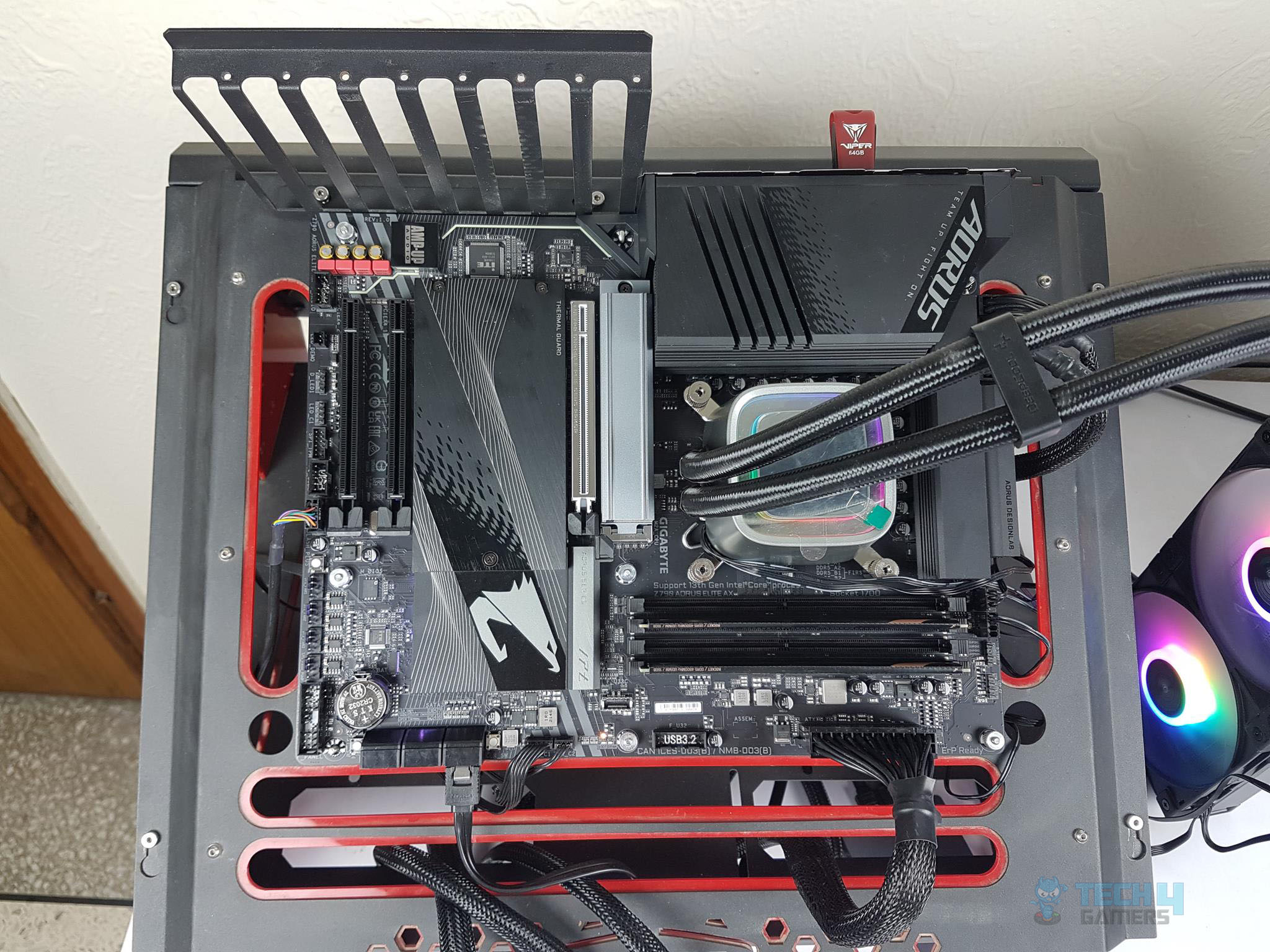
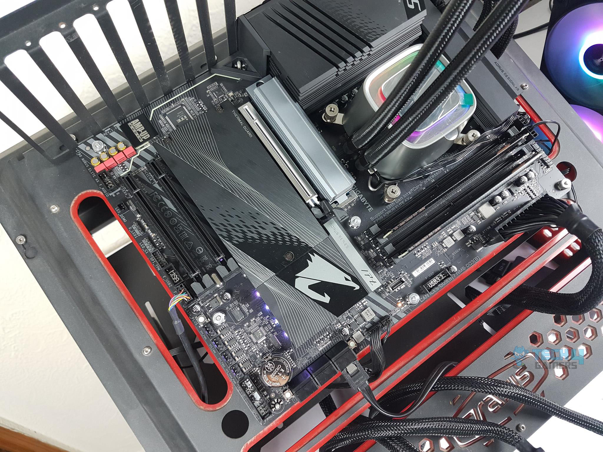
DIMM Slots
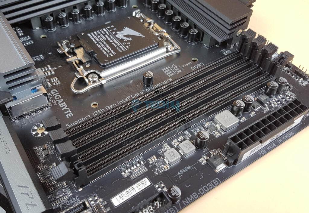
The Z790 AORUS ELITE AX motherboard has 4x DDR5-based DIMM slots which are not SMD stainless-steel reinforced. There is no anti-plate bending support. The DDR5 up to 7600MHz is supported (with BIOS update). By default, the board supports 4400 and 4800MHz. A total of up to 128GB RAM capacity is supported with a single stick density of 32GB. This is Dual Channel architecture and supports un-buffered DIMM 1Rx8/2Rx8/1Rx16 memory modules. They support XMP and AMD EXPO as well.
This board supports DDR5 Auto Booster to 5000MHz. This is a one-click operation that can be done in the UEFI/BIOS. The user can define and create their own SPD profile in Native and XMP 3.0 memory modules. One user-defined profile can be saved and loaded either locally or from/to an external storage device. This way the saved profile can be loaded on the other system and have that system configured in no time. The board also supports quick memory performance simulation based on user input clock and timing parameters.
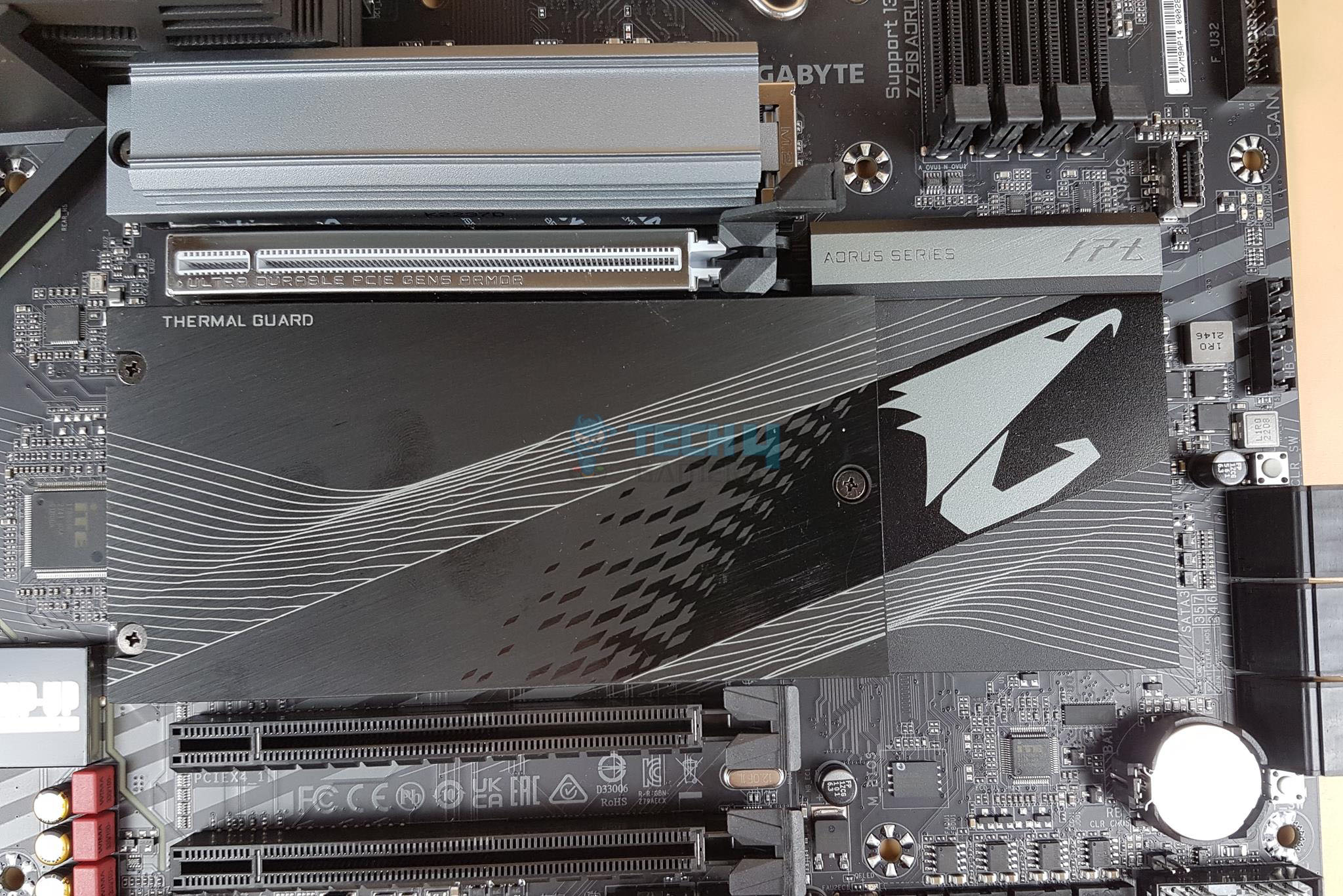
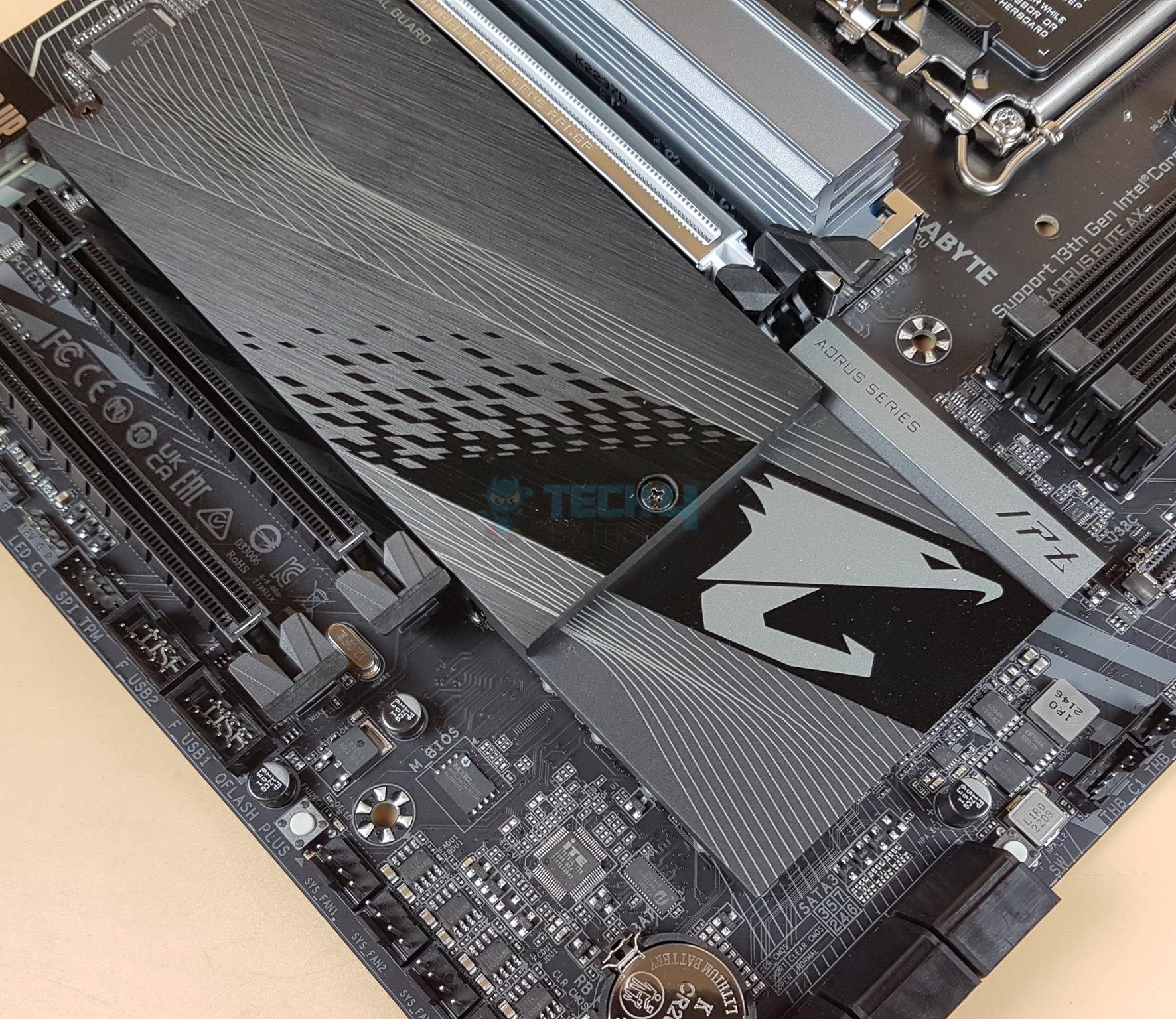
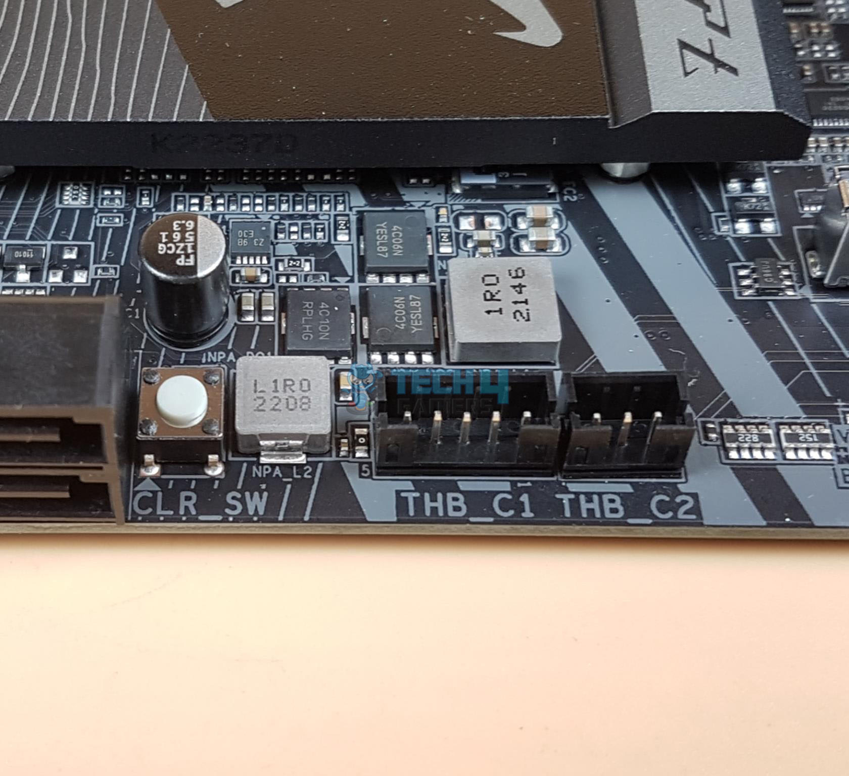
M.2 Ports and Thermal Guard
Following in the footsteps of the AMD ZEN 4, Intel has also introduced the M.2 Gen 5 support on the 13th generation platform. However, only the high-end models in Z790 from GIGABYTE provide this support. We have a total of 4x M.2 ports on this motherboard. Though they support the form factor of 22110, they are not Gen 5. All 4x M.2 ports are PCIe Gen 4. Only the top slot is wired with the CPU socket. The remaining 3 are wired with the chipset.
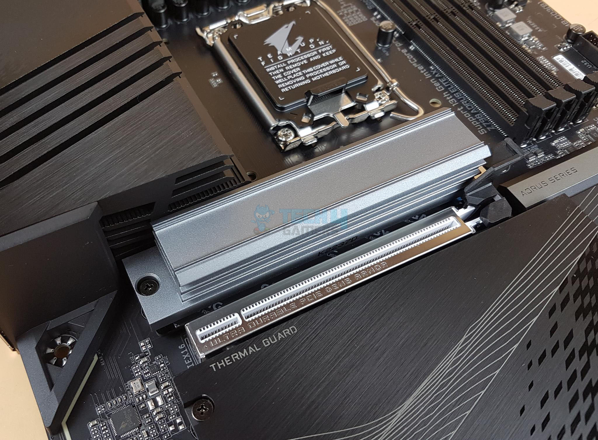
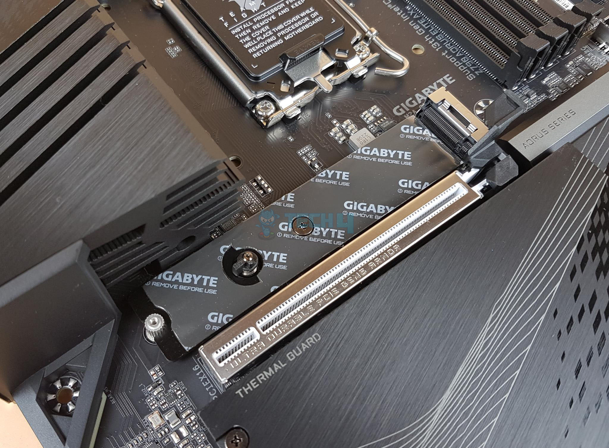
The above pictures show a thicker M.2 thermal Guard in a silver color finish and with the cover removed. This cover is on the topmost M.2 slot only. This is the only slot that features dual thermal pads.
We have a 2.5cm thick multi-layered cover providing an effective cooling solution for the Gen 4-based M.2 NVMe SSDs.
The above picture shows a single-piece, low-profile cover for the M.2 ports and the M.2 thermal cover removed from the motherboard. There are 3x pre-applied thermal pads on it.
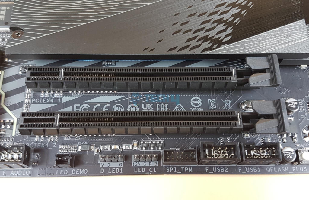
PCIe Slots and EZ-Latch Design
When it comes to the PCIe slots, this motherboard has 3x PCIe slots. I like how GIGABYTE has implemented the two bottom slots.
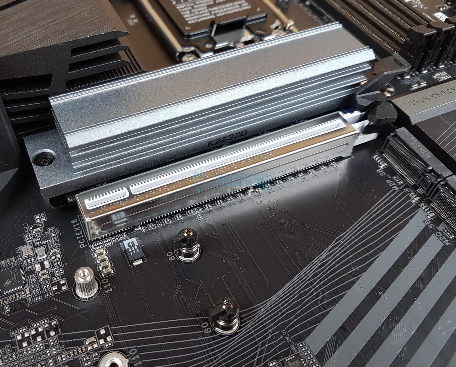
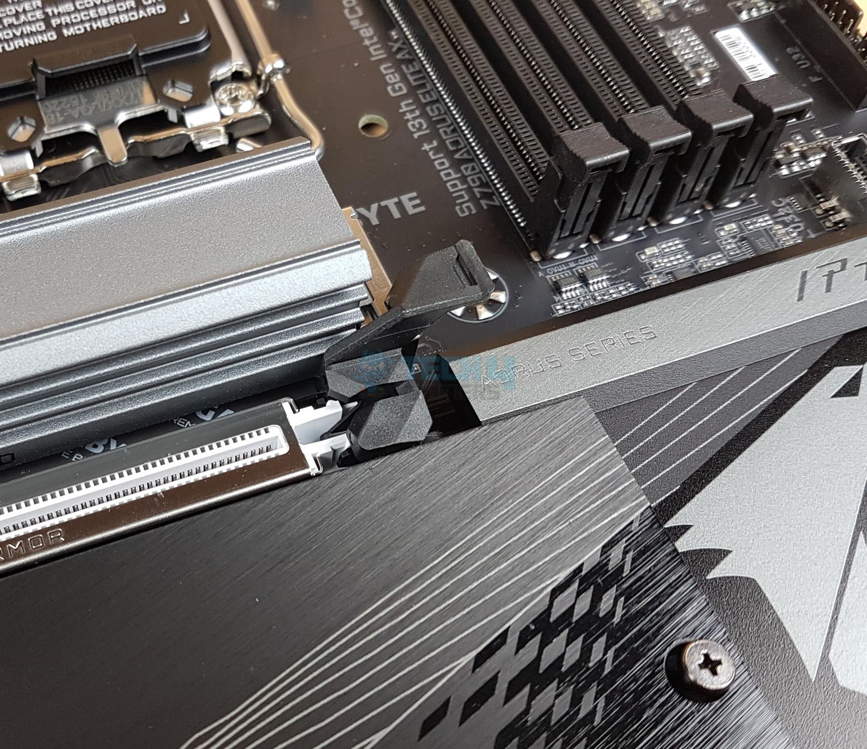
The top most PCIe slot is wired to the CPU socket and is a fully functional PCIe Gen 5 x16 slot with a theoretical bandwidth of 128GB/s. This slot is SMD stainless-steel reinforced. This Ultra Durable PCIe Armor Stainless steel provides reinforced tensile strength. As we have seen on the previous GIGABYTE motherboards, this motherboard is using double locking bracket for the topmost slot.
GIGABYTE has provided an extended PCIe locker which is implemented on top of the standard locker. This is what they refer to EZ-Latch which makes it convenient to remove the graphics card from the slot. Since this extended locker arm is extending the top NVMe slot, it is easier to access in otherwise the space-constrained area.
Z790 Chipset
Now, it is time to take a look at the Z790 chipset area.
There is an AROUS Falcon styling on the chipset cover. Please take a closer look as the M.2 thermal covers sit above the chipset cover. This would mean, you would need to remove the M.2 thermal cover in order to remove the chipset cover. There are 4x screws on the backside of the PCB. Removing them will release the cover.
Behold the Z790 chipset! We have a simple layout with a power delivery circuit on the right. The chipset has a passive cooling hinting at drawing a low power.
Audio Solution
The audio solution on this motherboard is adequate though nothing extraordinary. It is using RealTek ALC897 codec to drive the audio solution. This is just an ok solution which could have been better in my opinion.
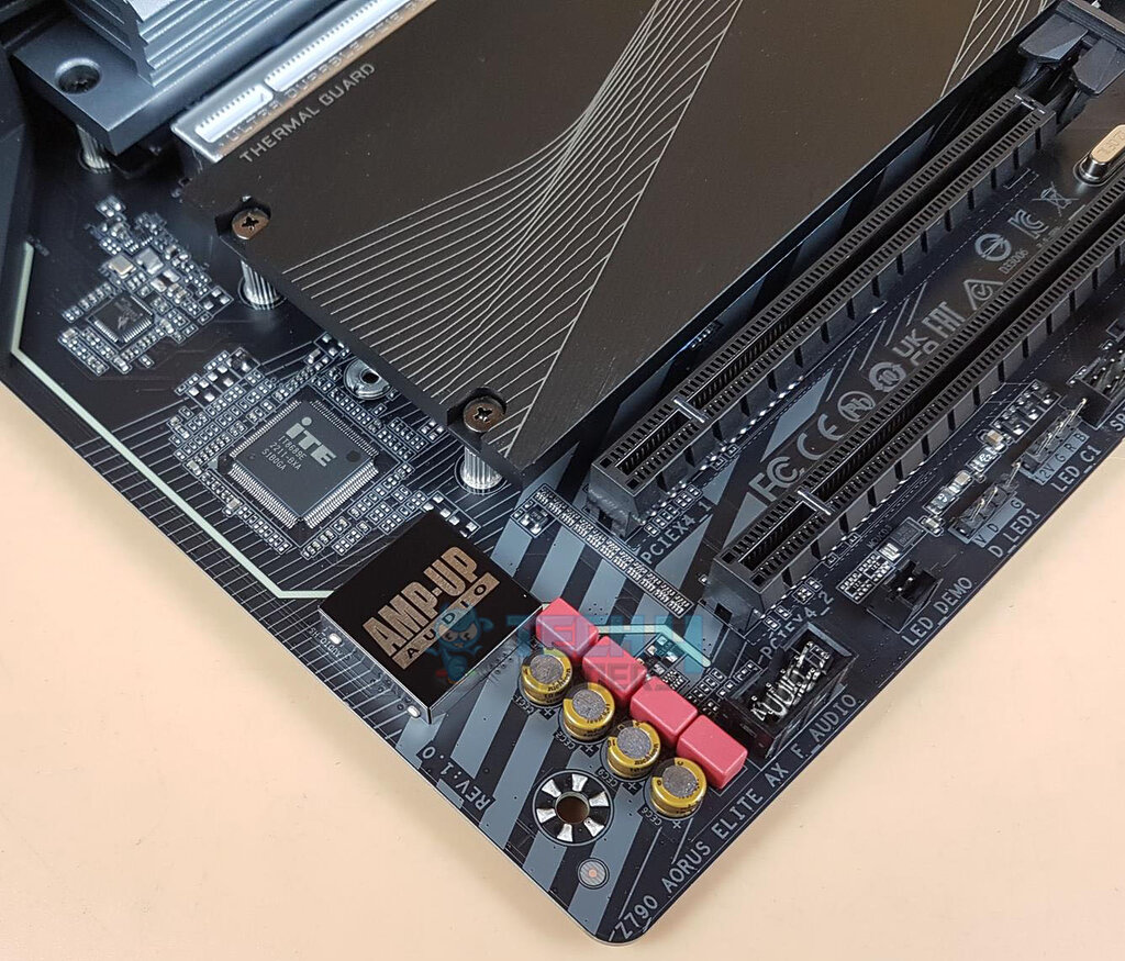
The above picture shows the well-shielded Audio circuitry. This motherboard is using 4x high-end WIMA capacitors along with Fine-Gold capacitors to drive the power of the circuit. This is not a Hi-Res Audio solution. AORUS motherboards feature an audio noise guard that essentially separates the board’s sensitive analog audio components from potential noise pollution at the PCB level.
Networking Connectivity
We have two main areas here:
- Wireless connectivity
- Wi-Fi
- Bluetooth
- Wired connectivity
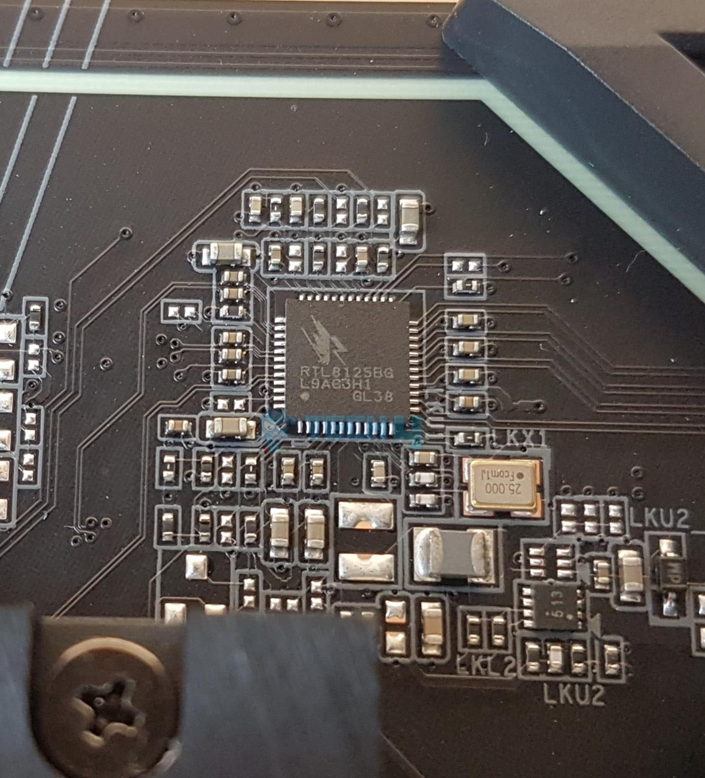
GIGABYTE has provided a single 2.5GbE LAN chip using RealTek RTL8125BG on this motherboard. There is a single RJ-45 port on the back panel for the wired network connectivity. The 2.5GbE provide roughly double the speed of that 1GbE connectivity for a better online gaming experience. The Ethernet port supports 10/100/1000/2500Mbps.
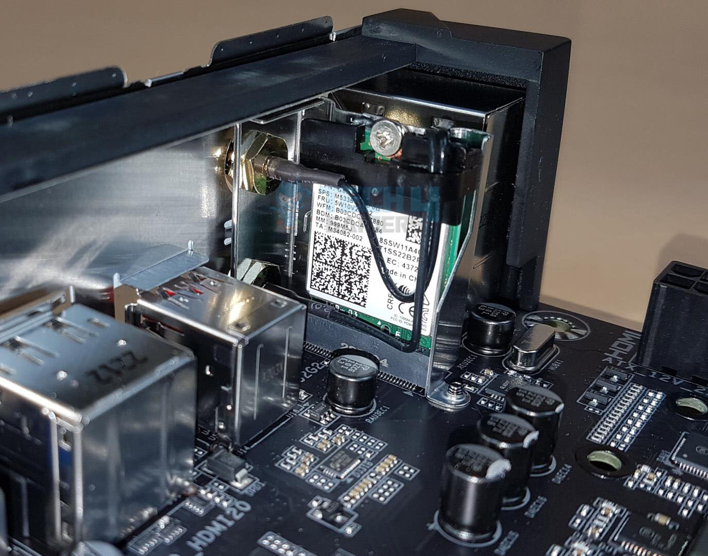
The Intel Wi-Fi module is implemented on the mSATA NGGF port on the rear I/O panel. The main driving force is the Intel AX211 chip capable of Wi-Fi 6E connectivity. The latest Wireless solution 802.11ax Wi-Fi 6E with a new dedicated 6GHz band enables gigabit wireless performance providing smooth video streaming, a better gaming experience, lesser dropped connections, and speeds up to 2.4Gbps. The motherboard features Bluetooth 5.3 protocol.
Some of the key benefits of Wi-Fi 6E compared to Wi-Fi 5 are:
- 40% faster speed for a smoother gaming/streaming experience
- 50% higher resolution for video game-related content
- Better battery life for VR devices
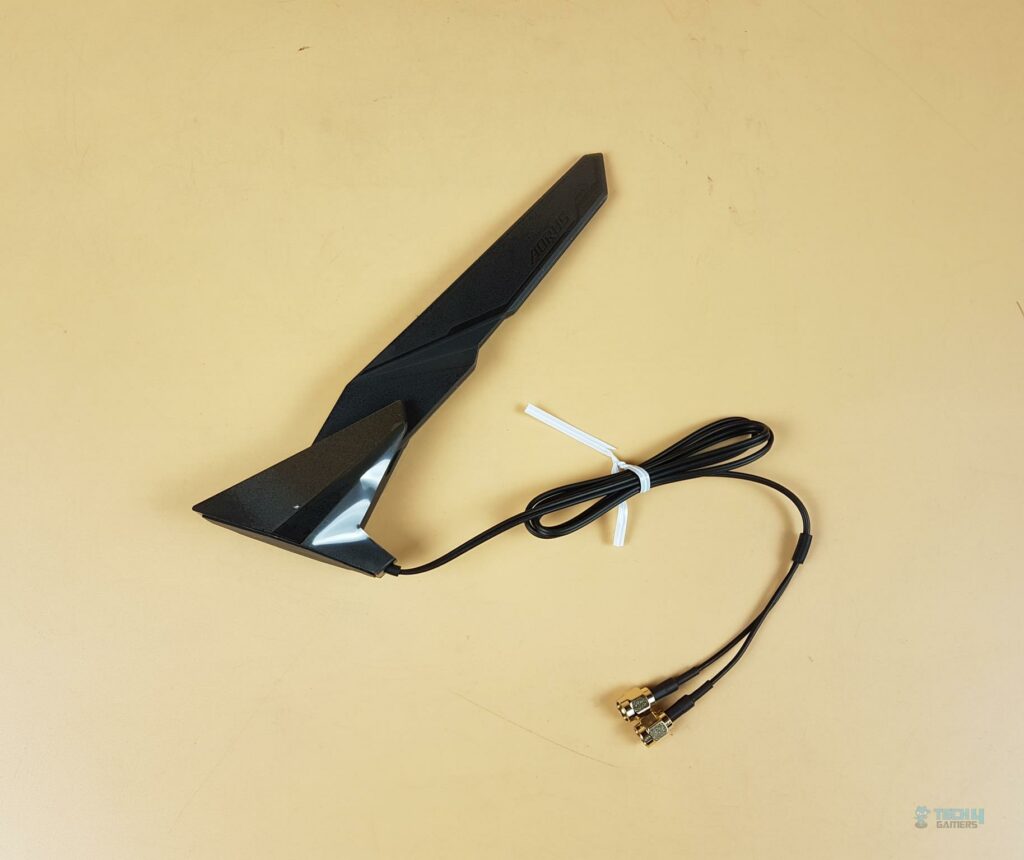
GIGABYTE has provided a Wi-Fi antenna in the box with a magnetic base for convenient mounting.
USB Connectivity
The USB connectivity is all provided by the chipset:
- 1 x USB Type-C® port on the back panel, with USB 3.2 Gen 2×2 support
- 1 x USB Type-C® port with USB 3.2 Gen 2 support, available through the internal USB header
- 2 x USB 3.2 Gen 2 Type-A ports (red) on the back panel
- 5 x USB 3.2 Gen 1 ports (3 ports on the back panel, 2 ports available through the internal USB header)
- Chipset+2 USB 2.0 Hubs: 8 x USB 2.0/1.1 ports (4 ports on the back panel, 4 ports available through the internal USB headers)
We can see the plethora of USB connectivity options on this motherboard.
This board has USB 3.2 Gen 2×2 over Type-C interface providing a theoretical bandwidth of 20Gbpson the rear I/O panel.
Internal Connectors
Now that we have covered the main features, functions, and design of the motherboard, let’s take a look at the internal connectors.
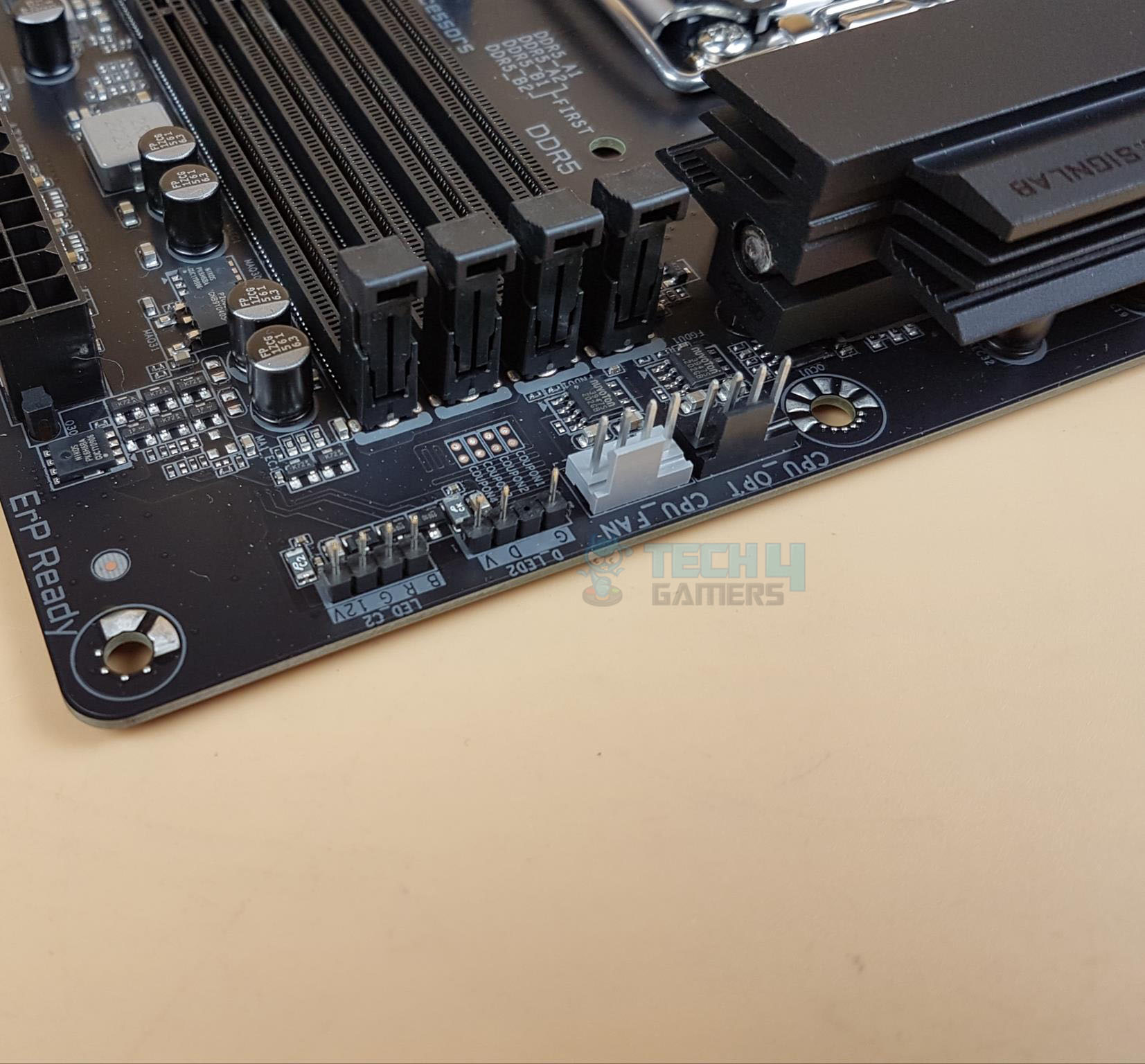
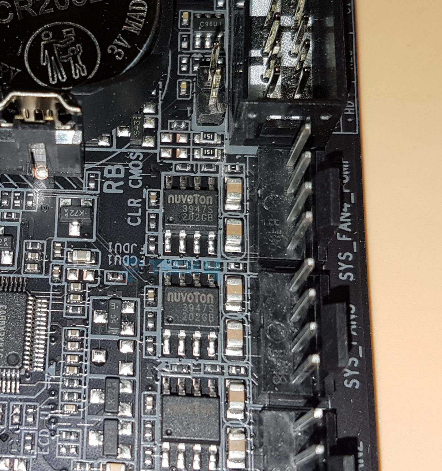
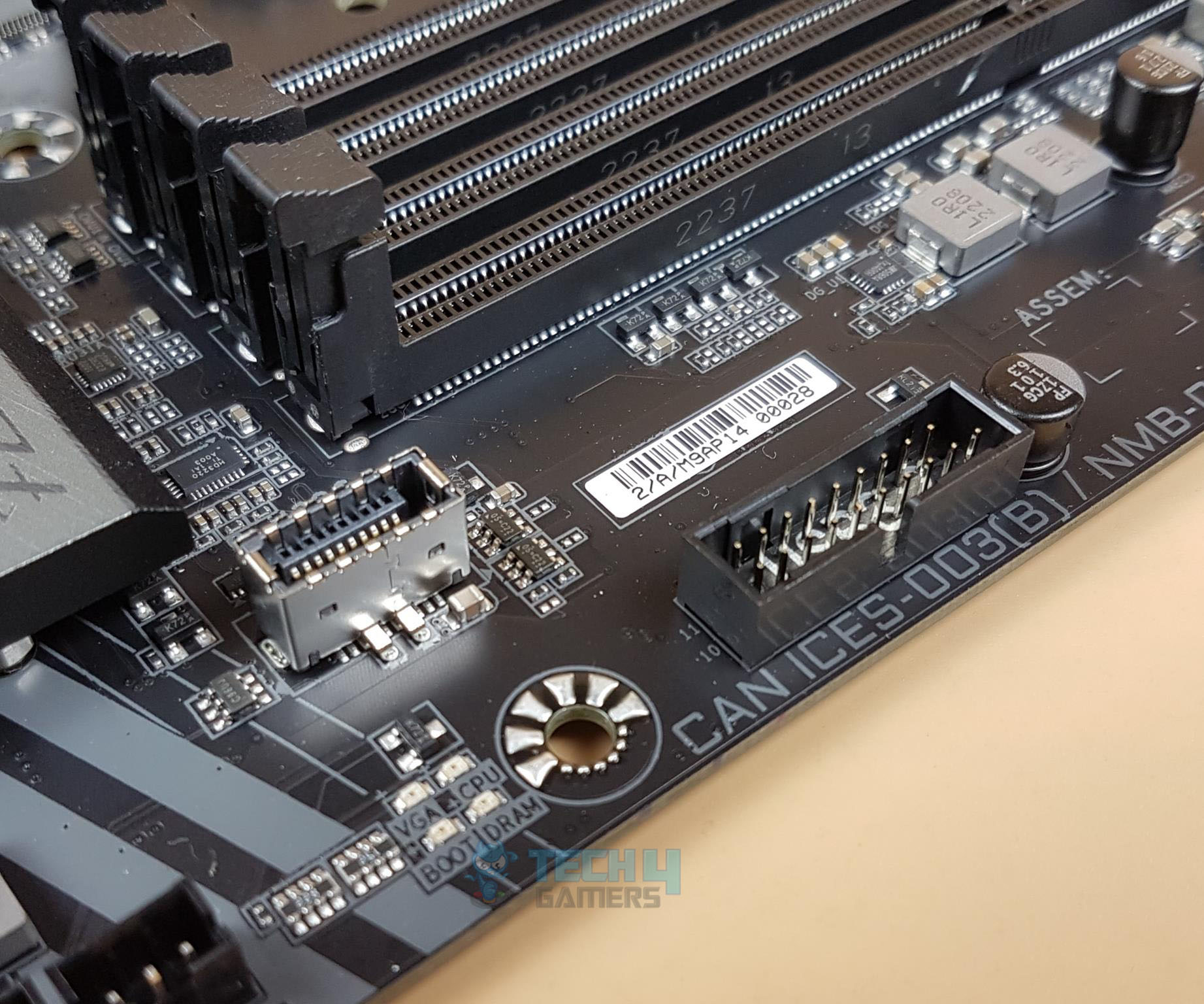
Starting from the right side, we have:
- 2-pin Reset CMOS Jumper
- System Panel Connector
- 4x 4-pin PWM System Fan Header
- Q-Flash Plus Button with LED
- 2x USB 2.0 Headers
- 1x 4-pin 12V RGB Header
- 1x 3-pin 5V RGB Header
- 1x LED Demo Jumper
- Front Panel Audio Header
This is a Rev 1.0 version of the motherboard. It is a bit surprising that there is no 4-pin fan/pump header on the side of the PCB. This would restrict the connectivity options.
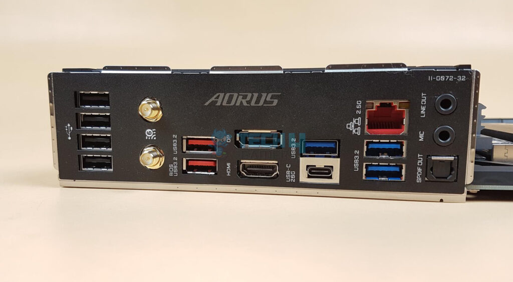
The following options are provided:
- 1 x USB Type-C® port, with USB 3.2 Gen 2×2 support
- 2 x USB 3.2 Gen 2 Type-A ports (red) [Use BIOS labeled port for BIOS Update via Q-Flash Button]
- 3 x USB 3.2 Gen 1 ports
- 4 x USB 2.0/1.1 ports
- 2 x SMA antenna connectors (2T2R)
- 1 x HDMI 2.0 port
- 1 x DisplayPort
- 1 x RJ-45 port
- 1 x optical S/PDIF Out connector
- 2 x audio jacks
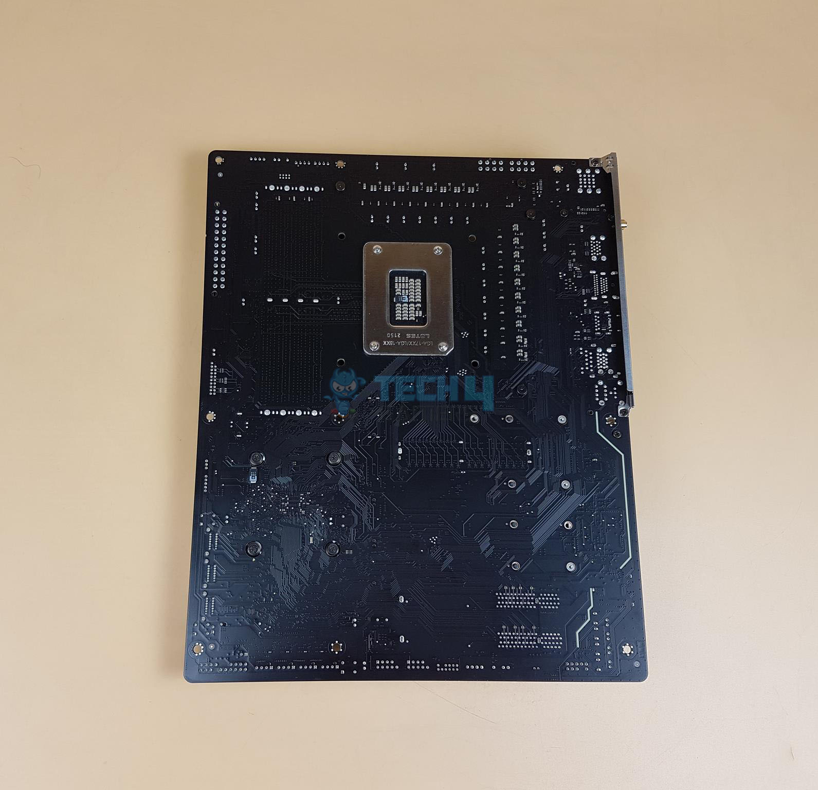
The above picture shows the backside view of the motherboard. The chipset screws have rubber washers between them and the PCB. You can also look at the PCB with all heatsink covers removed.
UEFI/BIOS
We have more or less the same interface and layout as we have seen in the past from GIGABYTE with a few changes.
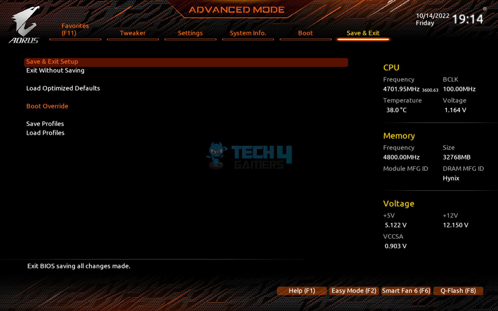


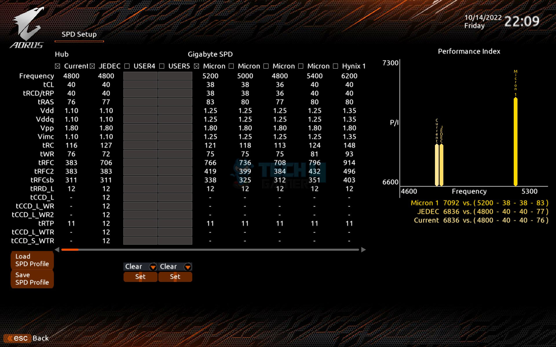
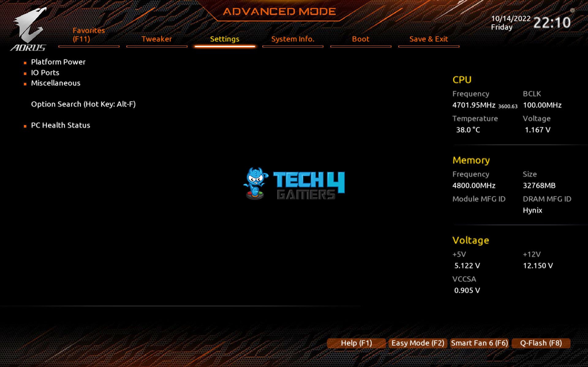

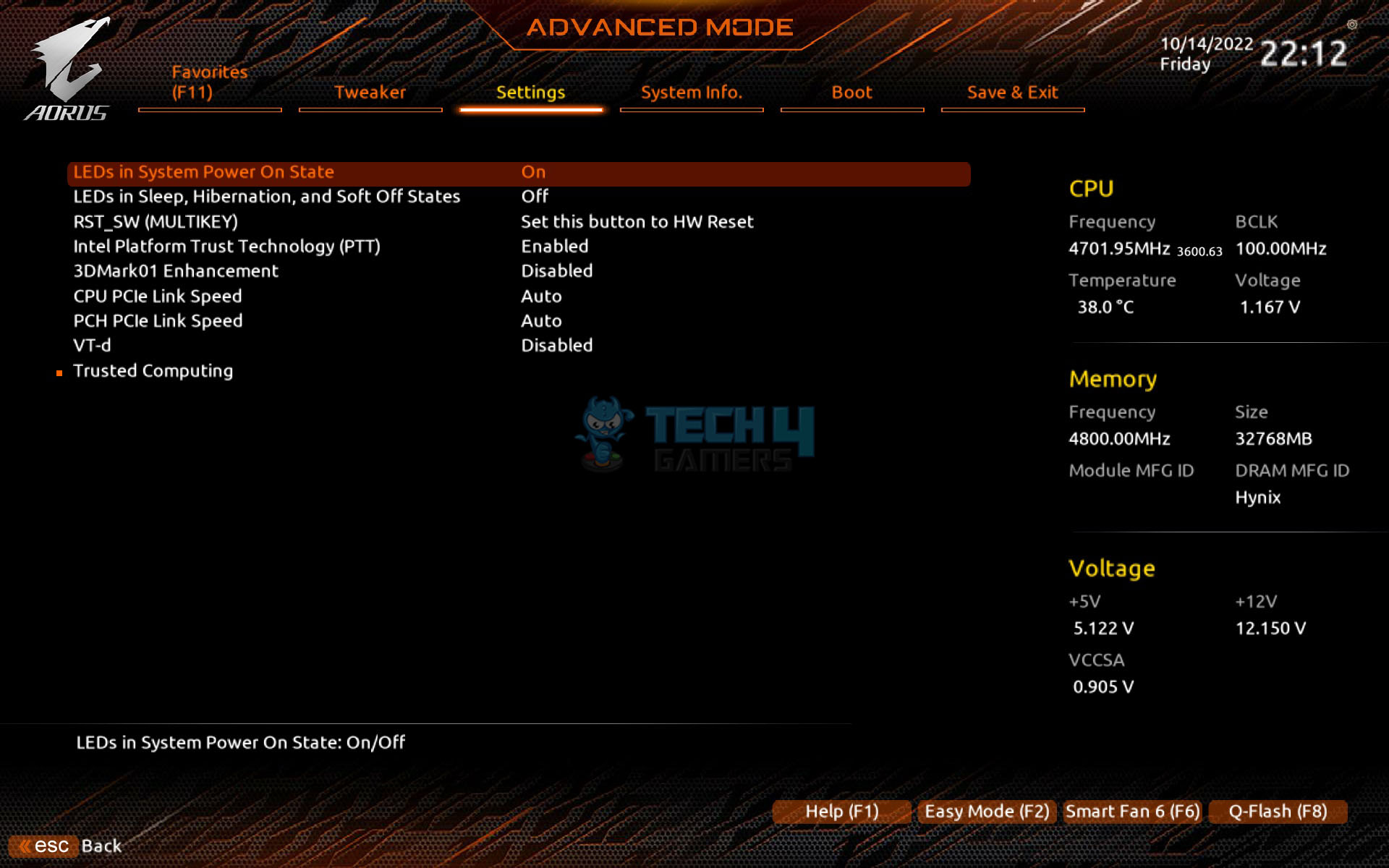

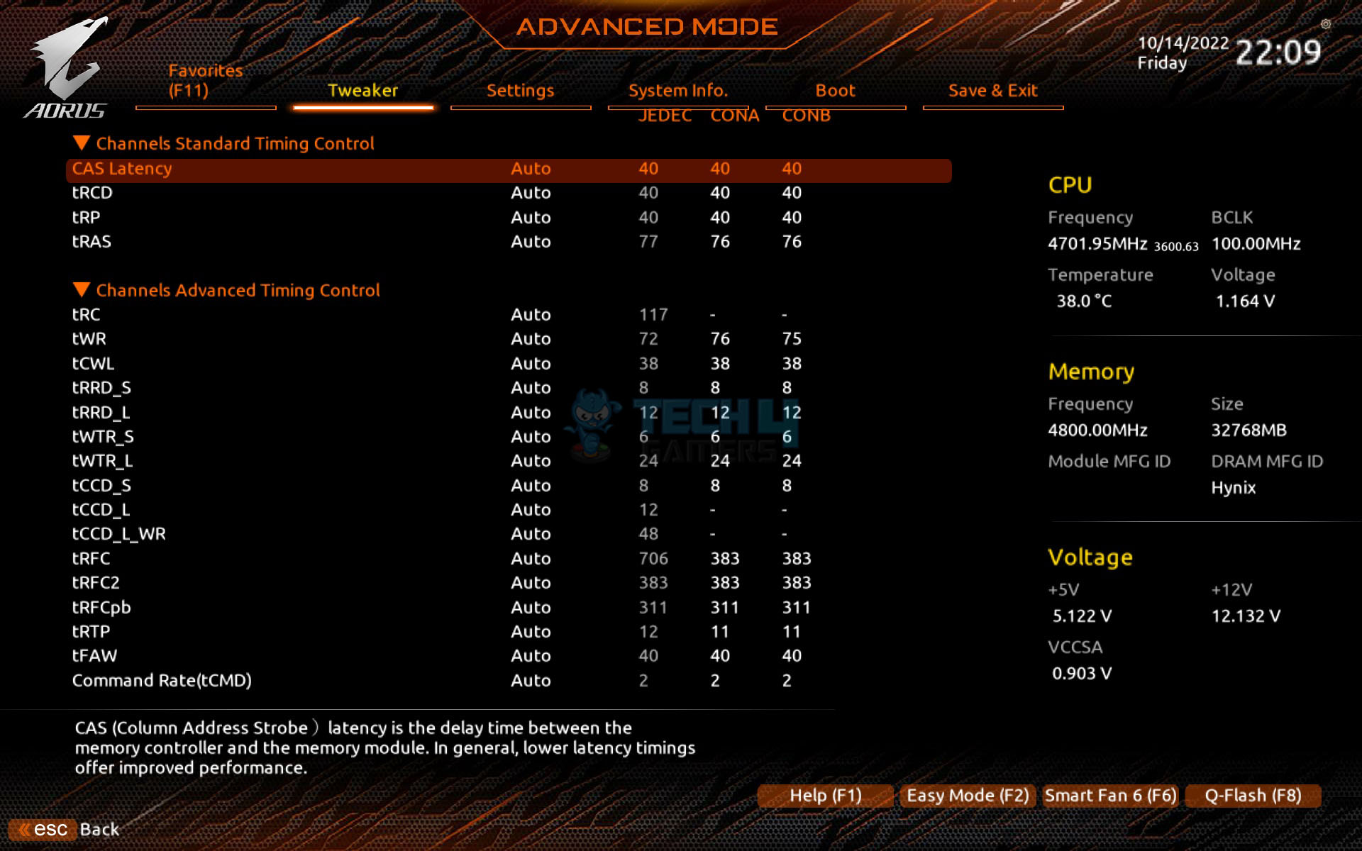
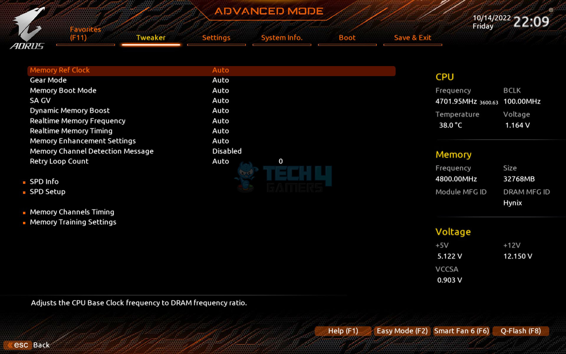
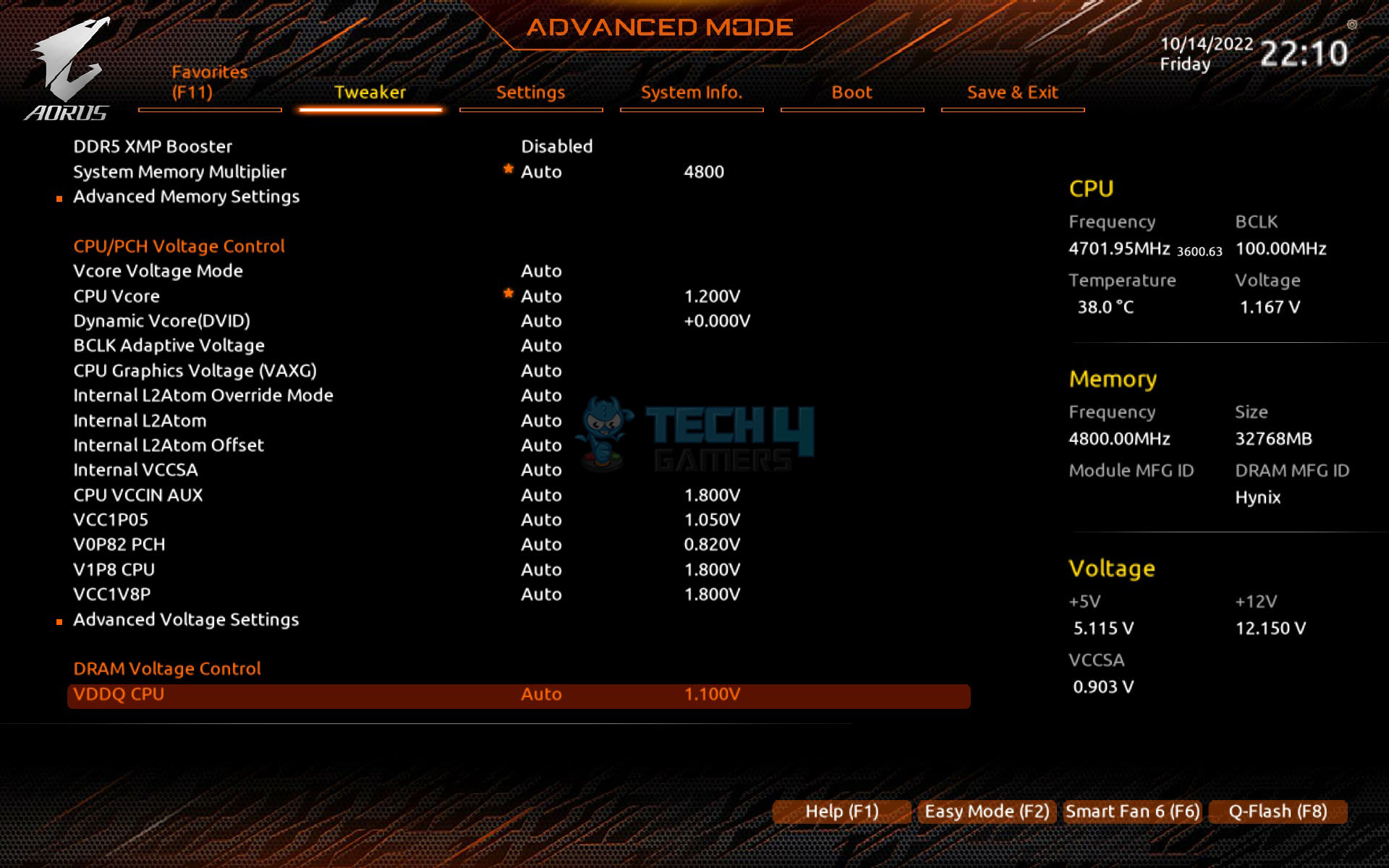

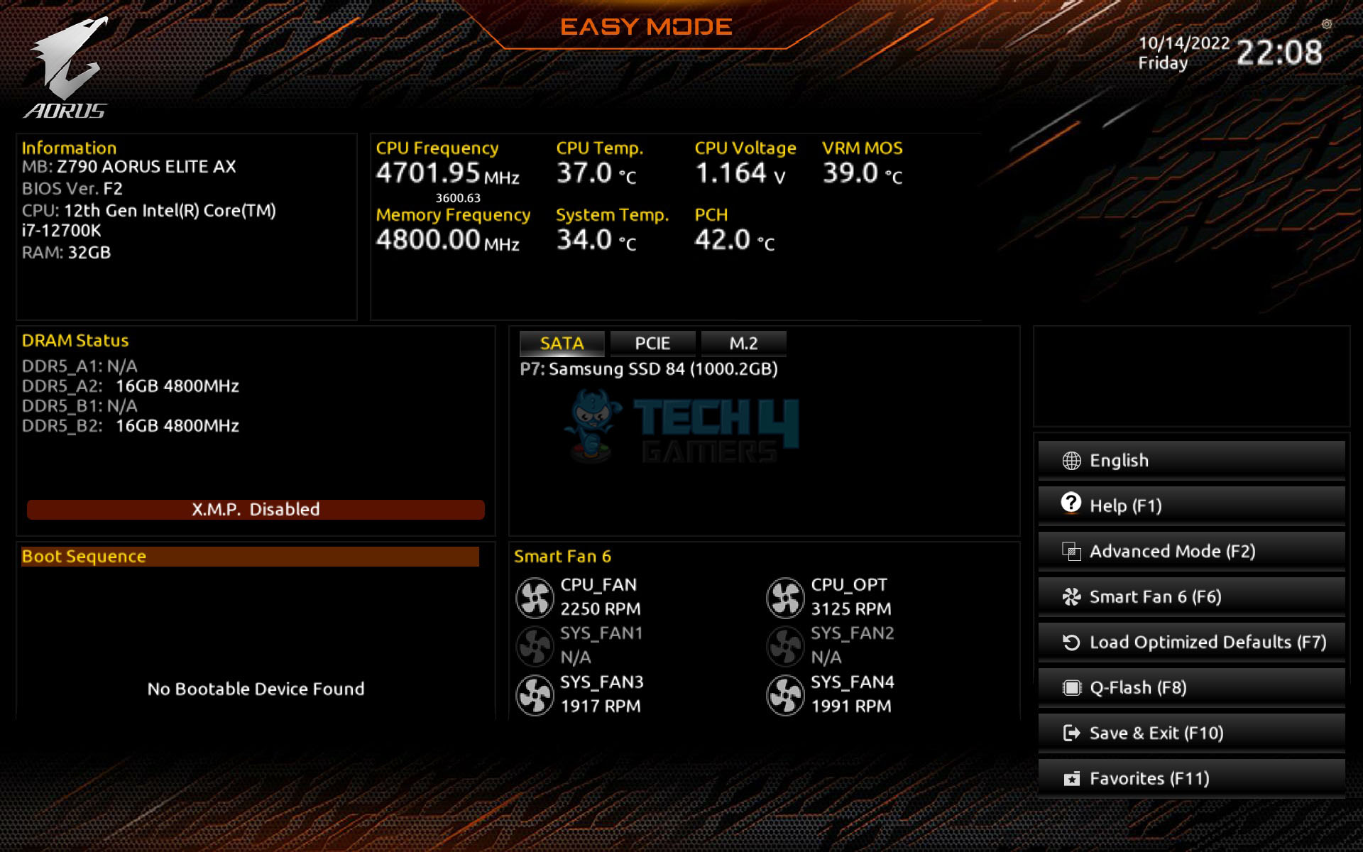
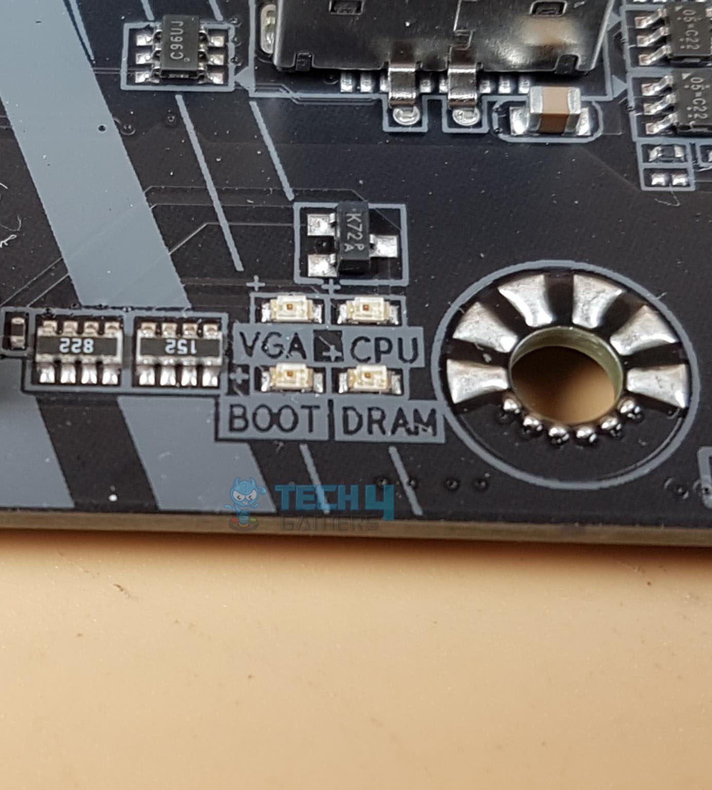
The BIOS is loaded in the Easy mode where the summary and current statistics are shown of the components. The Tweaker is the key area where the enthusiasts will be spending time tuning the system and overclocking. We have CPU and DRAM-related settings on one page. There is a plethora of DRAM settings that the advanced user/enthusiast can play with for extreme overclocking of the kits. The user can define custom profiles in the BIOS and save them for later use on even use on another motherboard.
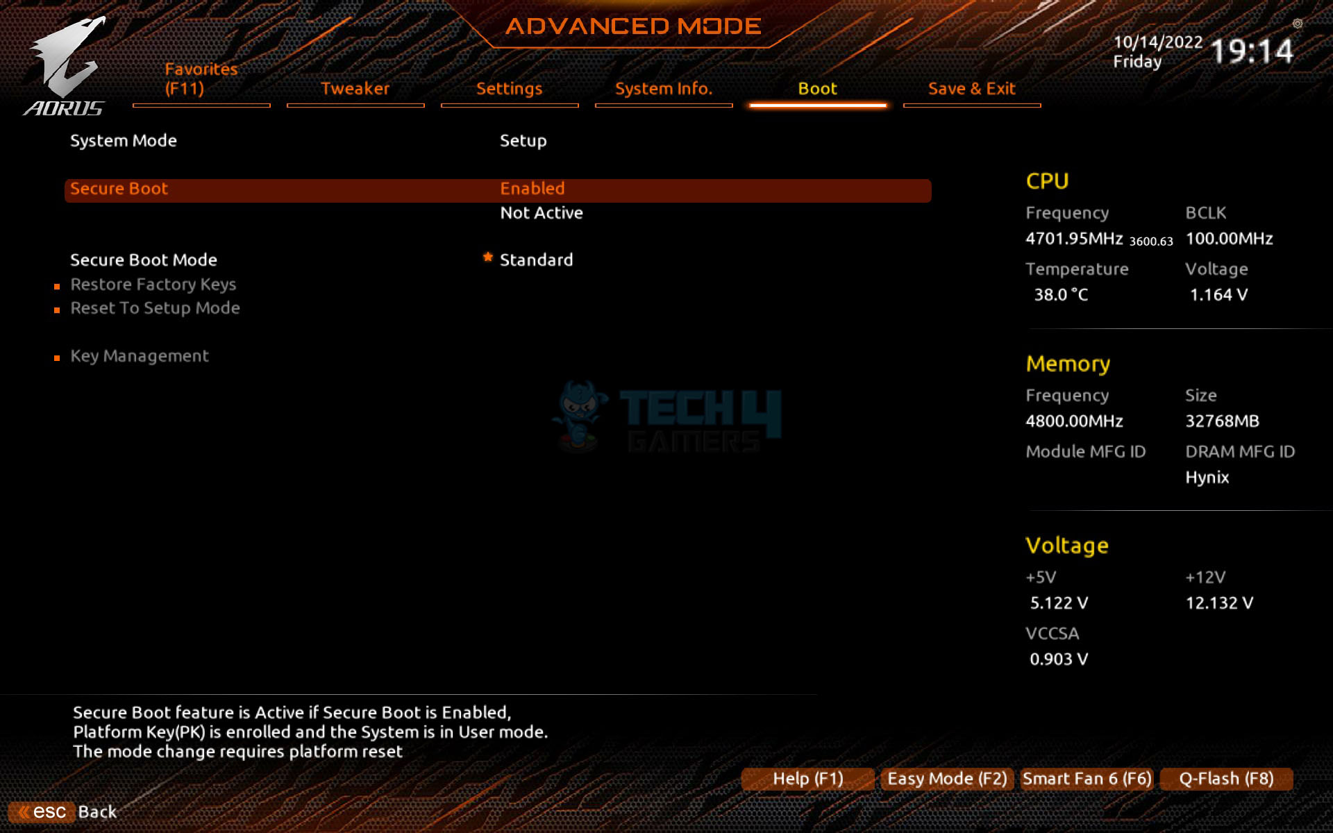
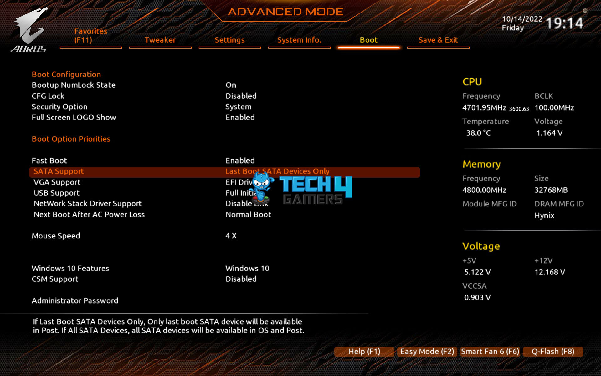
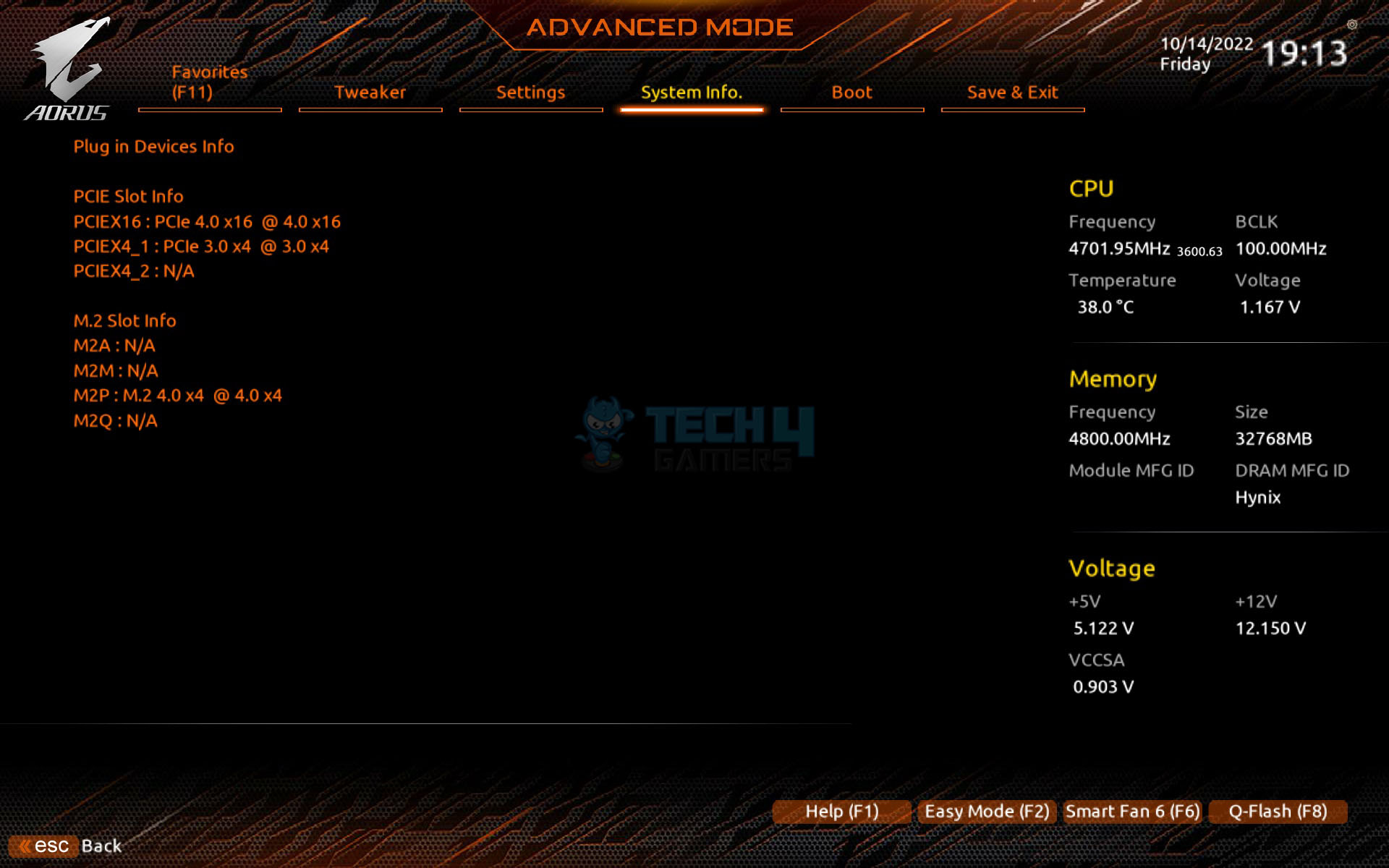
The Above 4G Decoding and Re-Size Bar are disabled by default. If you want to utilize the GIGABYTE Control Center, then better leave the Gigabyte Utilities Downloader Configuration enabled. The PCIe link speeds are on Auto. You can set them to the correct generation manually. The TPM is enabled by default. This is TPM (Trusted Platform Module) required for Windows 11 compatibility. The System information has the Q Flash located at the very bottom. The plugged-in devices can also be checked under this menu.
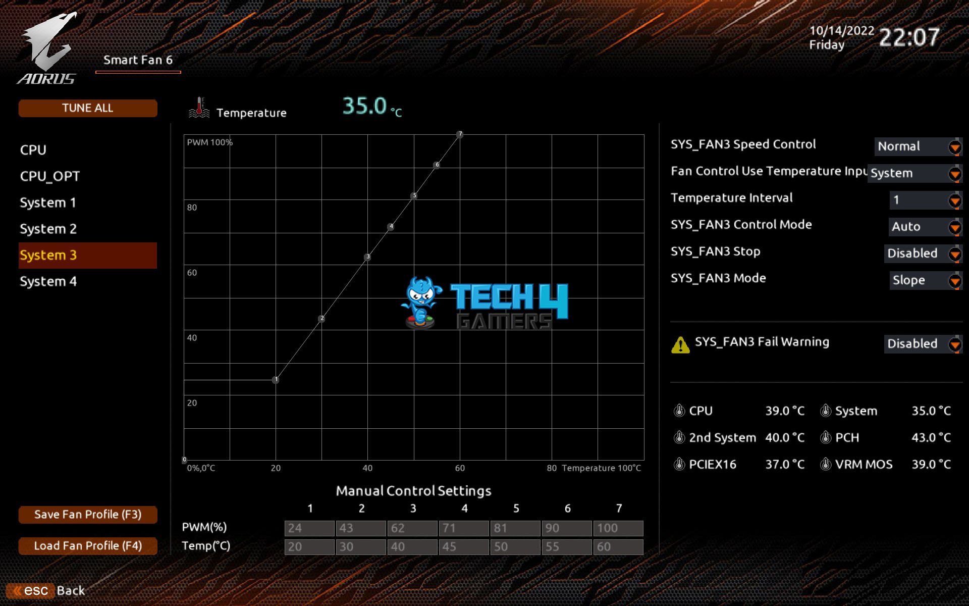
The Smart Fan 6 has some quite good changes. Now, we have Slope and Step modes available. We can set the fan to run at full speed with one click and we can set it to manual and define a custom fan curve which can be applied to the other fan headers as well. Pressing F3 will load a menu asking to save the fan settings in the BISO or on the external media. This can be retrieved regardless of the BIOS changes later on. The last page is the Save and Exit options. The user can define the profiles and load them later on. The optimized Defaults can also be loaded from here.
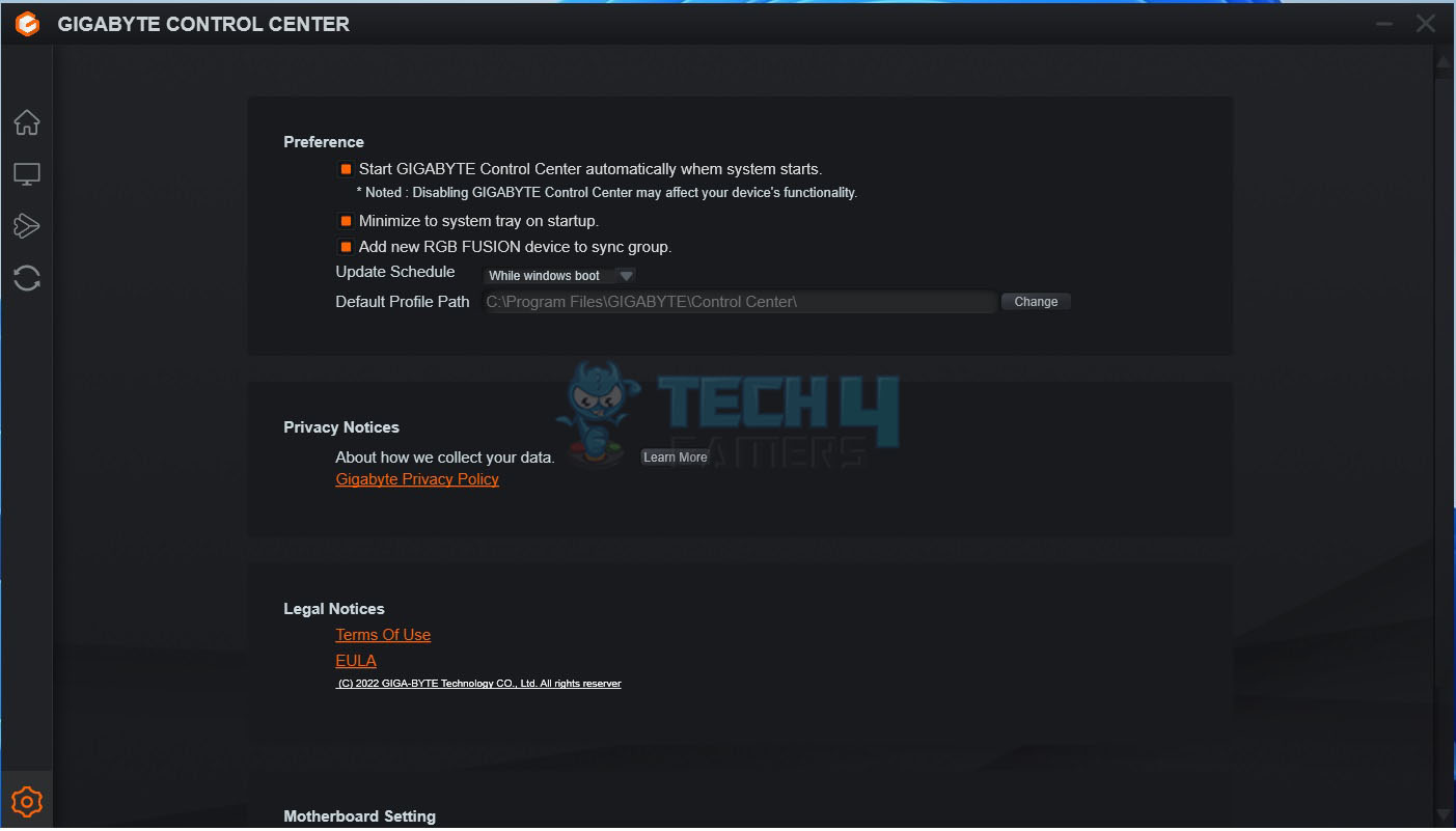
GIGABYTE Control Center
GIGABYTE has followed the industry trend and has now merged all the related utilities under one roof called GCC. As soon as the Windows is loaded, you will be presented with an option to download the GCC. Please note that it is not yet available on the website so your only chance is to download it when given the option.

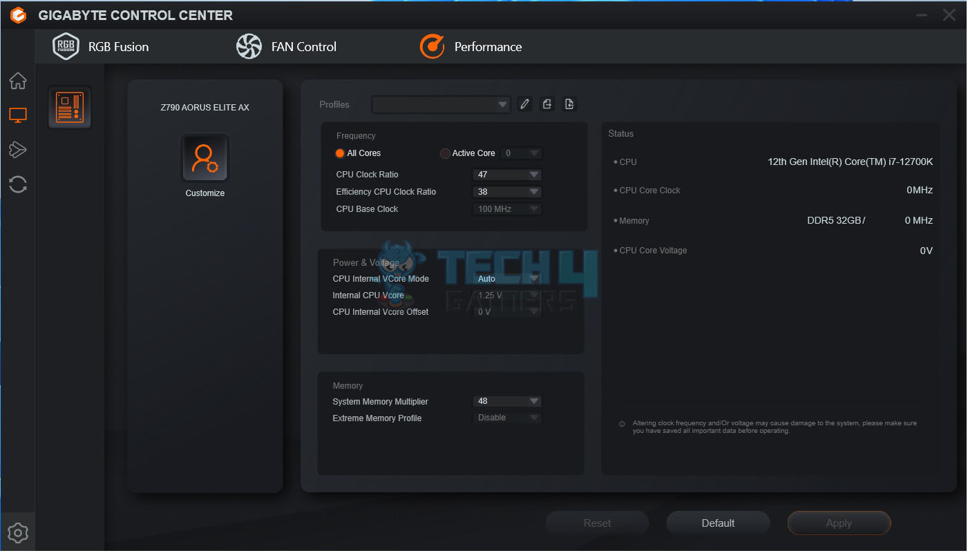
When launched, it will present you with the available updates and utilities. You can select which ones you need and start downloading them. They will be installed automatically. The main interface shows the motherboard and presents two options:
- RGB Fusion
- FAN Control
The RGB Fusion has almost the same layout as it was in the standalone version before. Remember, the onboard lighting solution is RGB (not digital). So, if you decide to sync all, the digital elements will also come in RGB mode. The user can define and control the fans’ behavior under the FAN Control option. The user can tune the system using the Performance option (but at their own risk).
Now that we have covered the UEFI/BIOS and GIGABYTE Control Center, let us turn to the testing of the motherboard.
Test Setup
The following test bench setup is used to test the performance of the motherboard:
- Intel i7 12700k [Auto, Stock] [We are still waiting to hear from Intel for the 13th-gen CPU]
- DeepCool LS720 [Fans and Pump at full speed]
- Sabrent Rocket 32GB DDR5 @ 4800MHz
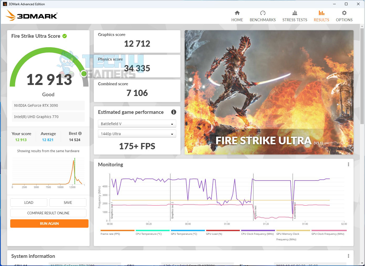
- MSI GeForce RTX 3090 Gaming X Trio
- be quiet! Straight Power 11 1000W Platinum
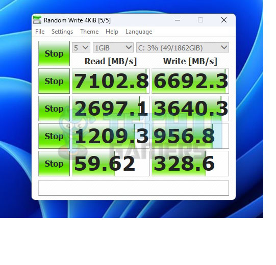
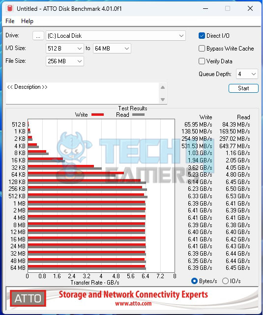
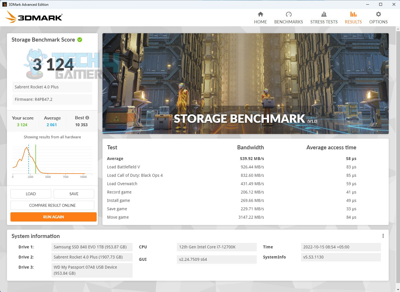
- Sabrent Rocket 4 Plus 2TB PCIe 4 NVMe SSD
- Samsung 840 EVO 1 TB SSD for the Games
- Praxis Wetbench
- 2x SilverStone Air Penetrator 120SK A-RGB fans
Microsoft Windows 11 x64 Pro 22H2 was used for all the testing. Nvidia 517.48 drivers were used for graphics card testing.
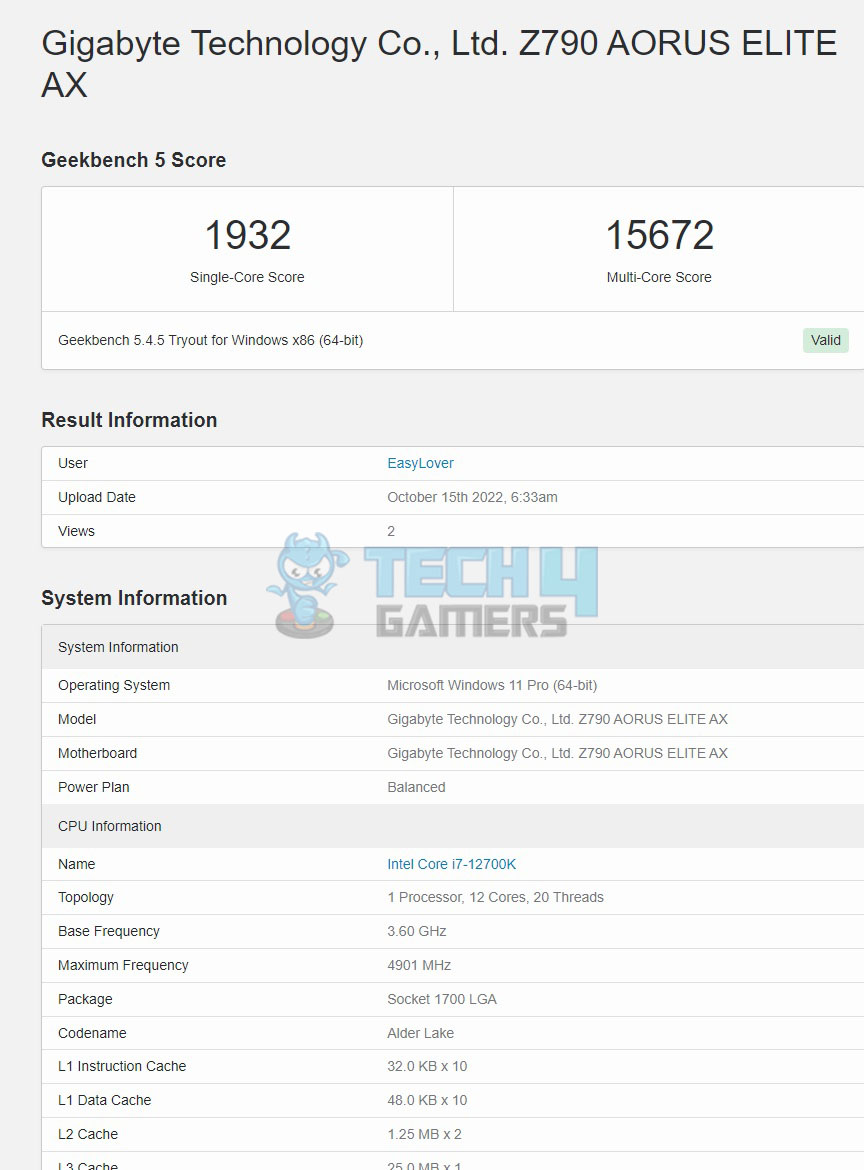
CPU-Z
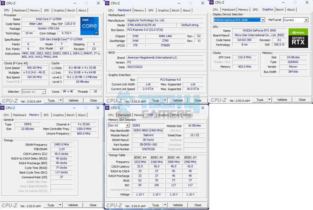
The above picture shows the CPU-Z values of the platform.
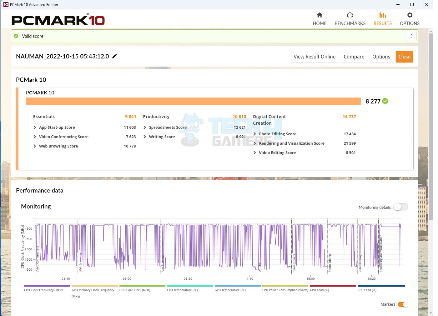
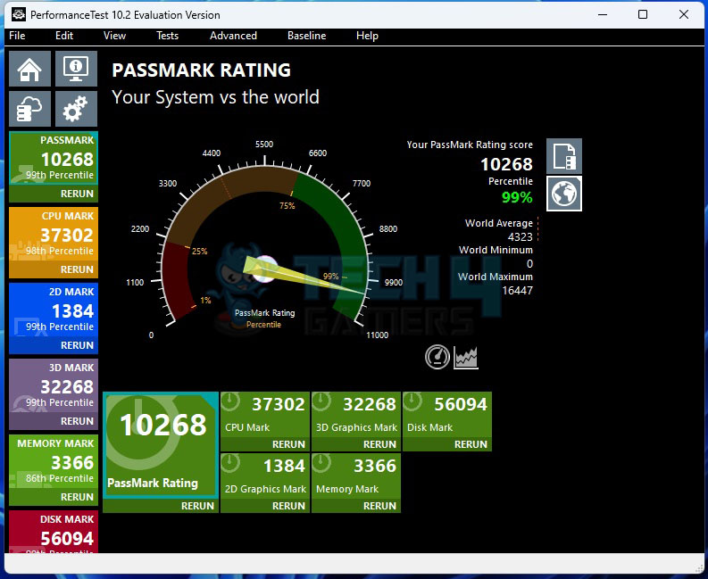
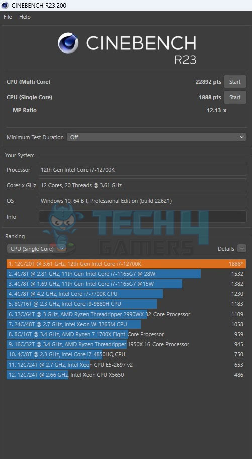
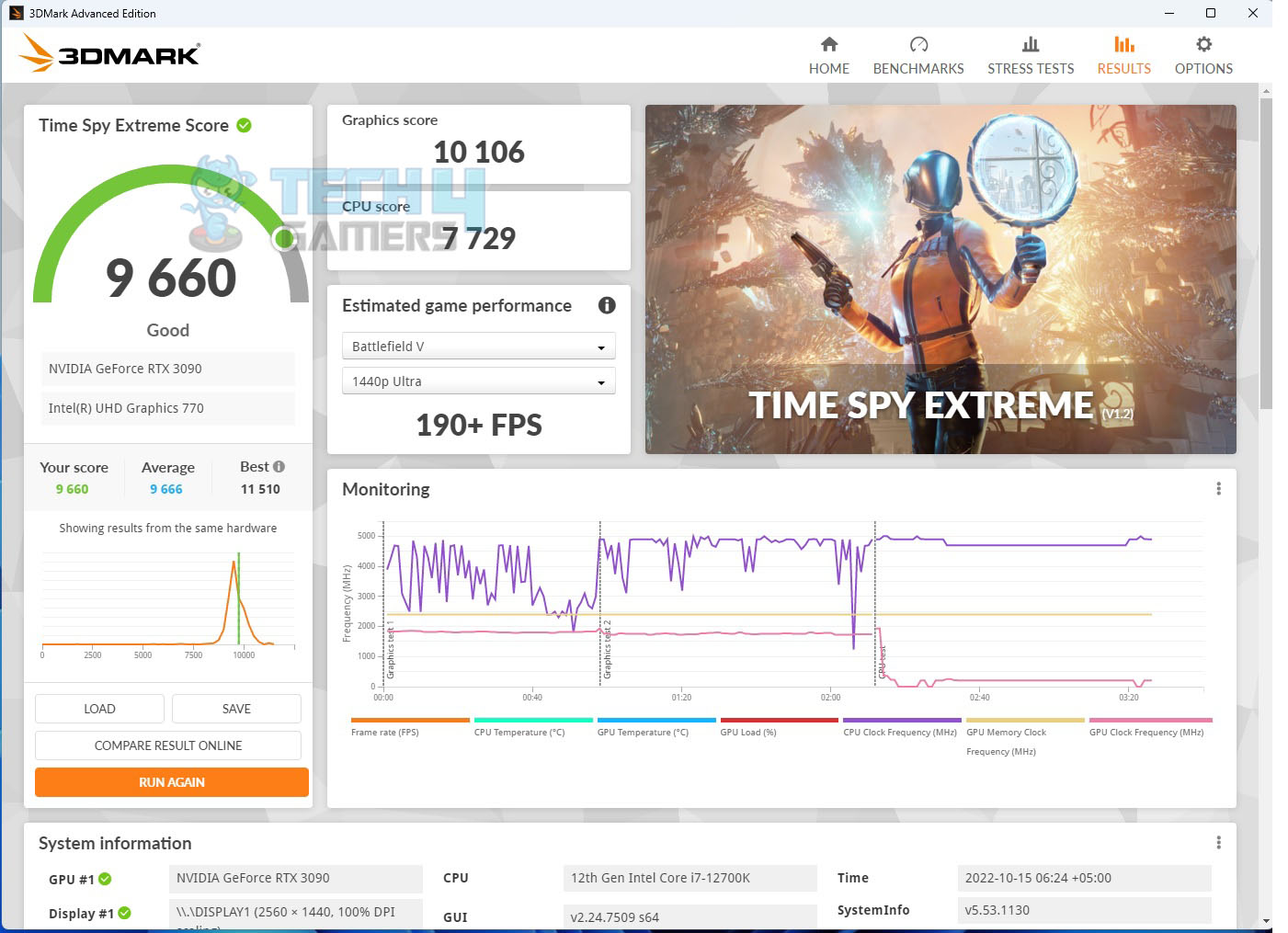
Overall System Performance
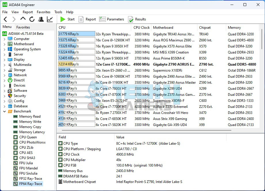
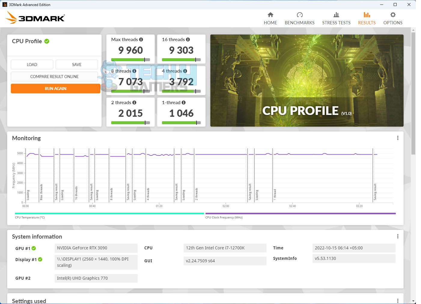
CPU Performance
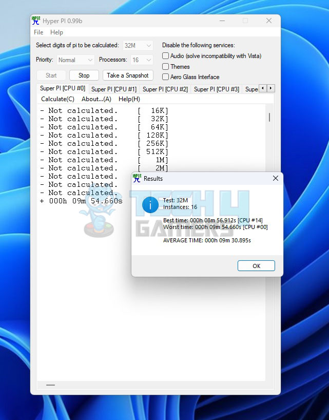

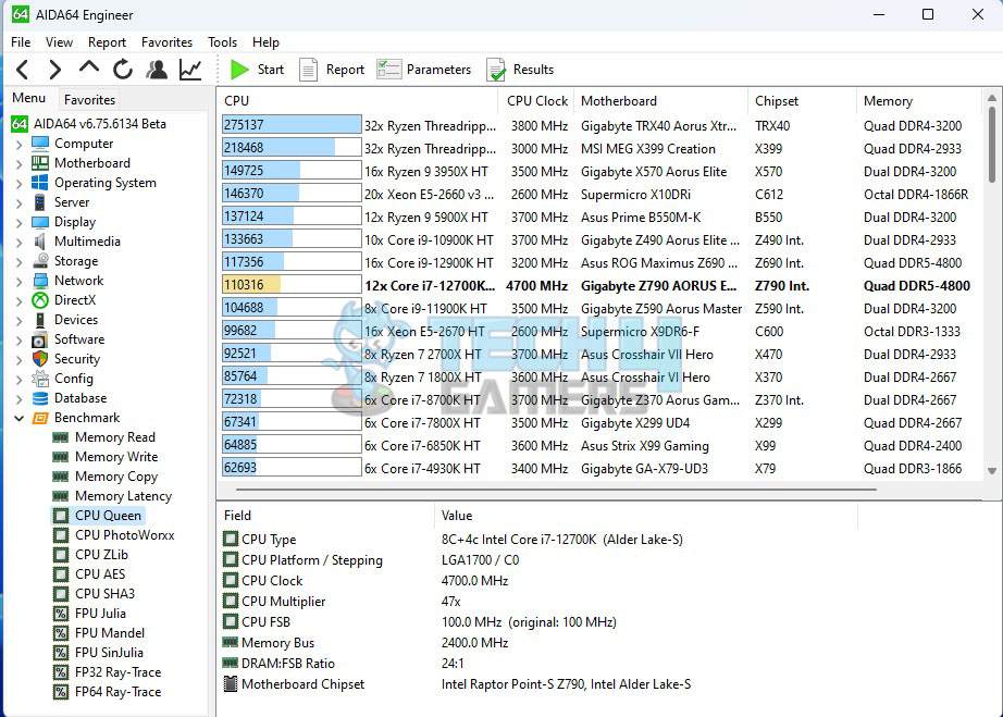
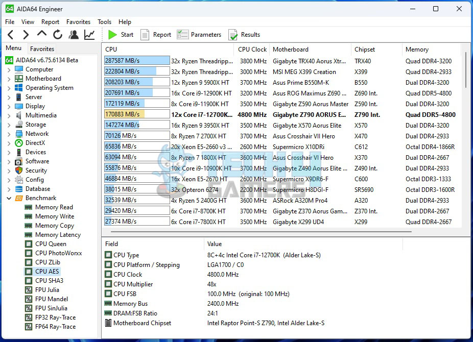
RAM Performance
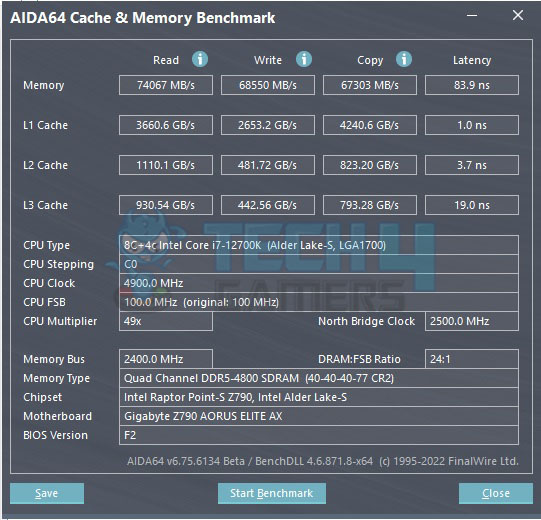
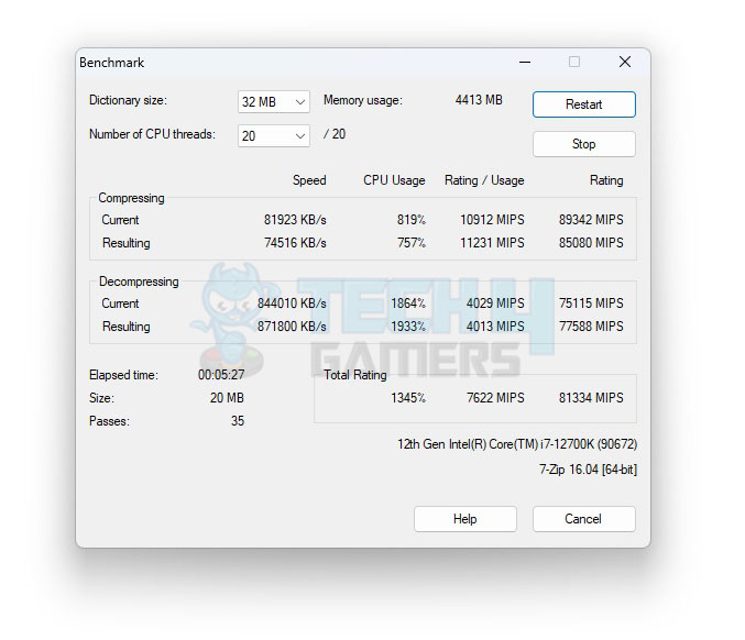
Storage Performance
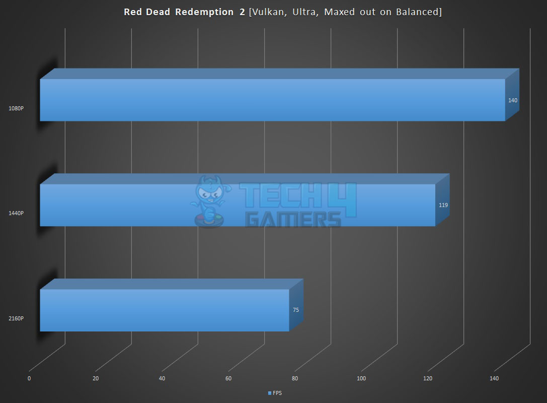
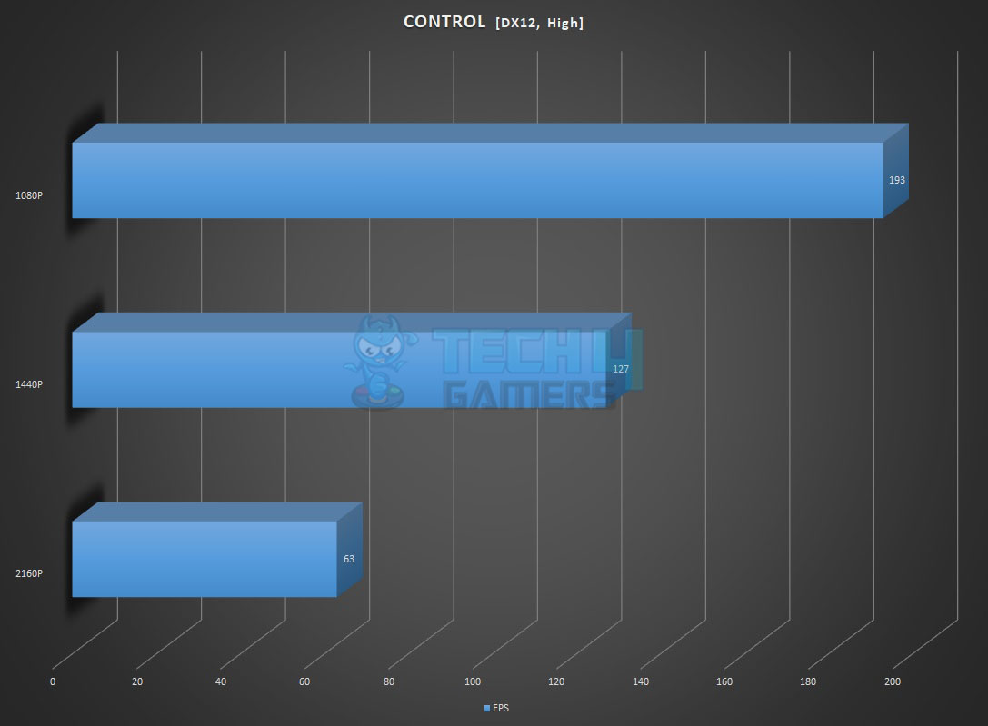
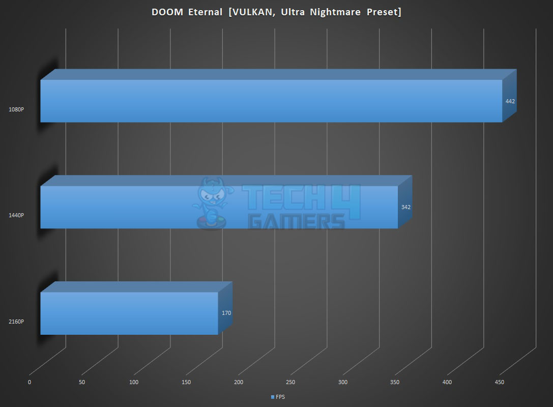
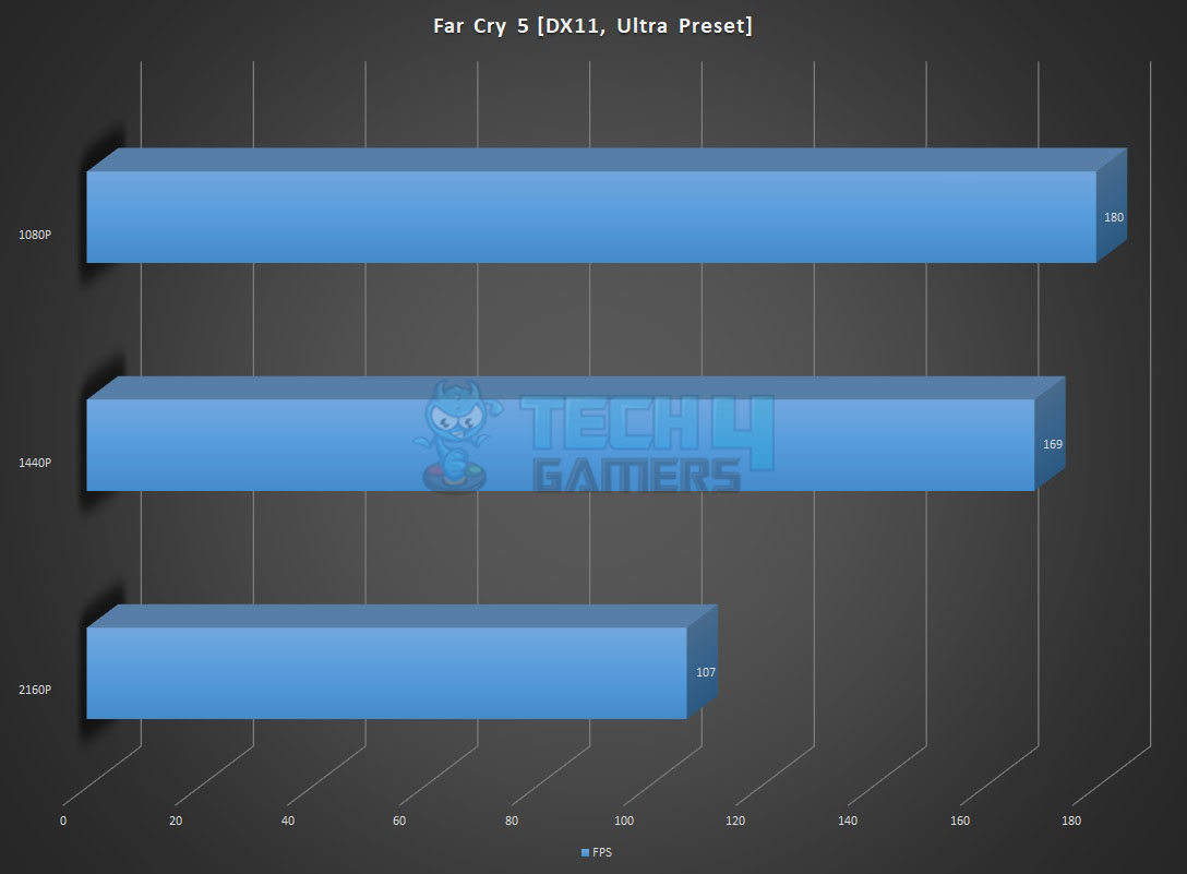
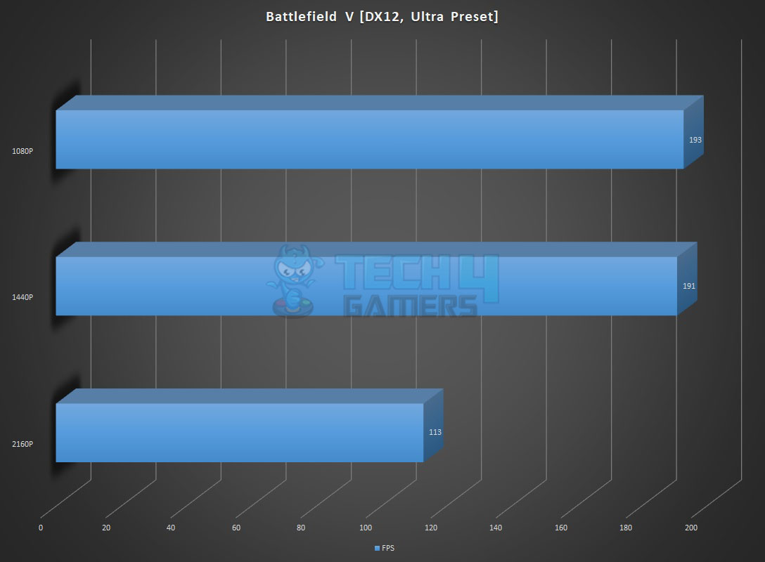
Gaming Performance
Power Consumption and Thermals
We have left all the settings in the UEFI/BIOS on auto and stock. We only set the Fans and pump speed to run at 100% all the time. The motherboard picked the Memory timing and frequency correctly since the Sabrent Rocket DDR5 kits are running at JEDEC default. The power mode was Balanced in the Windows. The system was left idle for 30 minutes, with HWInfo64 running in the background and recording the values. The ambient temperature was 29°C.
| CPU Package | RAM | NVMe SSD | Graphics Card | |
| Idle Temp | 32°C | 30°C | 32°C | 33.3°C |
| Idle Power Draw | 3.32W | 0.125W | N/A | 11.534 |
The frequencies on the cores were in the range of 800MHz+.
Next, the Cinebench R23 System Stability test was run for 30 minutes to record the thermals, power, and frequency behavior.
- The temperature of the CPU was 81°C with a VCore value of 1.296V. The frequencies were in the range of 4.7GHz on P-Cores and 3.8GHz on E-Cores. The package power draw was 169.885W.
- The graphics card under gaming load was drawing near 395W power with a maximum temperature of 75° We used a custom fan curve for the graphics card so the fans were running at high speed.
- The Sabrent Rocket 4 Plus NVMe SSD was doing 60°C under load.
The SilverStone Air Penetrator 120SK A-RGB fans were blowing focused air toward the graphics card, NVMe ports, and CPU socket area at full speed.
Thermal Imaging
We have used the Hti HT18 Thermal camera to record the thermals of the VRM area of the motherboard under load using a 30-minute run of Cinebench R23 on the stock settings.
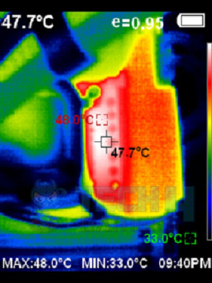
The MOSFETs were operating at around 48°C at an ambient of 30°C.
Should You Buy It?
Buy It If
You want a great value-for-money board: The Z790 AORUS ELITE AX, thanks to its impressively good pricing and a balanced set of features, manages to offer an unbelievably good bang for the buck.
You are after a good amount of performance: Backed by a 16+1+2 VRM structure and plenty of cooling support, the GIGABYTE Z790 AORUS ELITE AX packs a powerful punch that makes it a great contender for a performance-focused build.
Don’t Buy It If
Having a PCIe 5.0 M.2 slot is a must: Since it only comes with PCIe 4.0 M.2 slots, you may feel like skipping it if you’re after Gen5 SSD support.
Final Thoughts
With Intel’s 13th generation platform, we tested GIGABYTE’s Z790 AORUS ELITE AX motherboard. It showcases a sleek design, powerful power phases, and a feature-rich setup. The Intel LGA1700 socket supports both 12th and 13th-generation CPUs. This motherboard includes 4x DDR5 DIMM slots, 3x PCIe slots (one Gen-5 x16 and two Gen-4 x4), and 4x M.2 NVMe Gen4 ports.
We find 6x SATA ports, numerous USB ports, Wi-Fi 6E, Bluetooth 5.3, and a 2.5GbE LAN port. We appreciated the TMOS-based heatsinks for efficient cooling and the EZ-Latch for easy access. RealTek ALC897 drives the audio.
In our tests, the motherboard performed robustly across various applications, making it a strong contender in the mainstream market. The Z790 AORUS ELITE AX excels in storage, gaming, and network connectivity, though the audio is just okay. Overall, it’s a solid, balanced board that should appeal to many users.
Thank you! Please share your positive feedback. 🔋
How could we improve this post? Please Help us. 😔
Feedback By:
[Hardware Reviewer & Editor]
Meet Nauman Siddique, a highly experienced computer science graduate with more than 15 years of knowledge in technology. Nauman is an expert in the field known for his deep understanding of computer hardware.
As a tech tester, insightful reviewer, and skilled hardware editor, Nauman carefully breaks down important parts like motherboards, graphics cards, processors, PC cases, CPU coolers, and more.
- 15+ years of PC Building Experience
- 10+ years of first-hand knowledge of technology
- 7+ years of doing in-depth testing of PC Hardware
- A motivated individual with a keen interest in tech testing from multiple angles.
- I majored in Computer Science with a Masters in Marketing
- Previously worked at eXputer, EnosTech, and Appuals.
- Completed Course in Computer Systems Specialization From Illinois Tech
Get In Touch: nauman@tech4gamers.com