 Threads
GIGABYTE X670E AORUS MASTER
Should You Get GIGABYTE X670E AORUS MASTER?
The GIGABYTE X670E AORUS MASTER has more than what meets the eye. In its brilliance, this motherboard packs the features that one would need to drive their high-end needs in computing. We are impressed with every bit of it. It not only has top-notch performance but quite some style as well. GIGABYTE has covered all the major corners and left no stone unturned. If you are aiming for a high-end PC setup using the new Ryzen 7 series CPUs then this motherboard or its bigger brethren AORUS XTREME has got you covered.
Hours Tested: 17

Overall
-
Performance - 9/10
9/10
-
Design - 9/10
9/10
-
Features - 8.5/10
8.5/10
-
Value - 8/10
8/10
Pros
- Beefy Heatsink
- 16+2+2 Digital Power Phases
- PCIe Gen 5 X16 Slot
- PCIe Gen 5 M.2 Ports
- USB Type-C Gen 2 and 2×2 ports
- USB Type-C with Alt Mode for DP
- Wi-Fi 6E
- Debug LED
- Power Button
- Backplate
Cons
- Expensive
- CMOS Battery Removal


Today, I will be testing the GIGABYTE X670E AORUS MASTER. It is a performance-packed motherboard, and I expect it to be right at the top of other high-end X670E motherboards.
Regardless, let’s get into the review to see how it performs in the real world.
Key Takeaways
- The GIGABYTE X670E AORUS MASTER is a high-end motherboard designed for enthusiasts and gamers, offering robust performance, extensive features, and future-proofing for AMD Ryzen 7000/9000 Series builds.
- You should buy the GIGABYTE X670E AORUS MASTER if you’re a gamer, a content creator, or someone who likes to overclock.
- You should not buy the GIGABYTE X670E AORUS MASTER if you’re on a tight budget.
Here are the key specs:
| CPU | AMD Socket AM5, supports AMD Ryzen™ 7000 / 8000 Series Processors |
| Chipset | AMD X670 |
| Memory | Supports DDR5- 8000(OC) MT/s memory modules; 4 x DDR5 DIMM sockets, up to 192 GB; Dual channel; AMD EXPO™ and XMP support |
| Onboard Graphics | 1 x DisplayPort, 1 x USB Type-C® (USB 3.2 Gen 2, DisplayPort 1.4), 1 x HDMI (2.1) |
| VRM | 16+2+2 |
| LAN | Intel® 2.5GbE LAN chip (2.5 Gbps/1 Gbps/100 Mbps) |
| Wireless Communication | Intel® Wi-Fi 6E AX210 (PCB rev. 1.0) / AMD Wi-Fi 6E RZ616 (MT7922A22M) (PCB rev. 1.1), BLUETOOTH 5.3 / 5.2 |
| Expansion Slots | 1 x PCIe 5.0 x16, 1 x PCIe 4.0 x4, 1 x PCIe 3.0 x2 |
| Storage Interface | 4 x M.2 connectors (varied support for PCIe 5.0/4.0), 6 x SATA 6Gb/s connectors, RAID 0, 1, 10 support |
| Form Factor | E-ATX; 30.5cm x 26.9cm |
Last Updated:
- June 15, 2024: We have changed the formatting to improve readability.
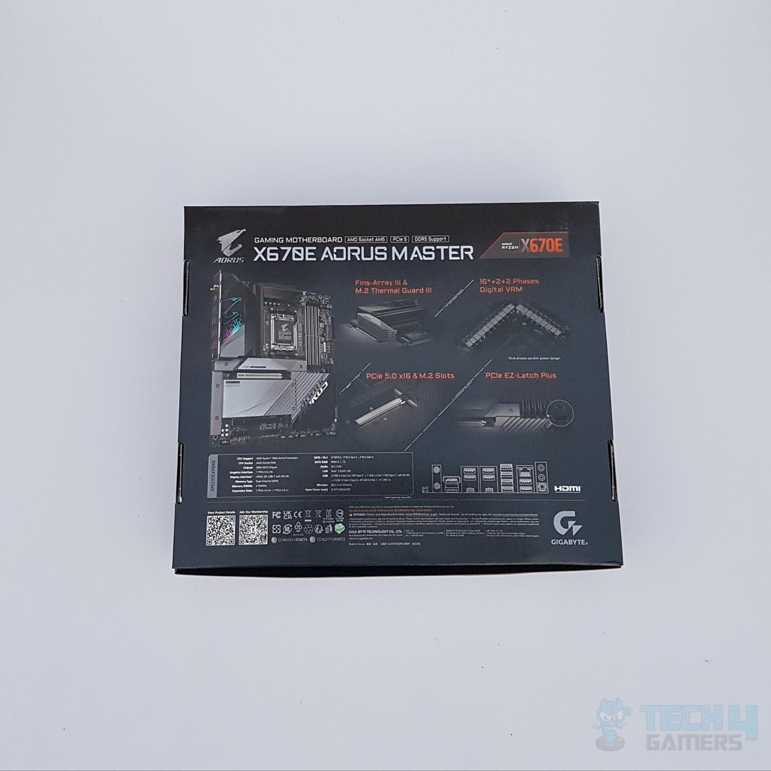
Packaging And Unboxing
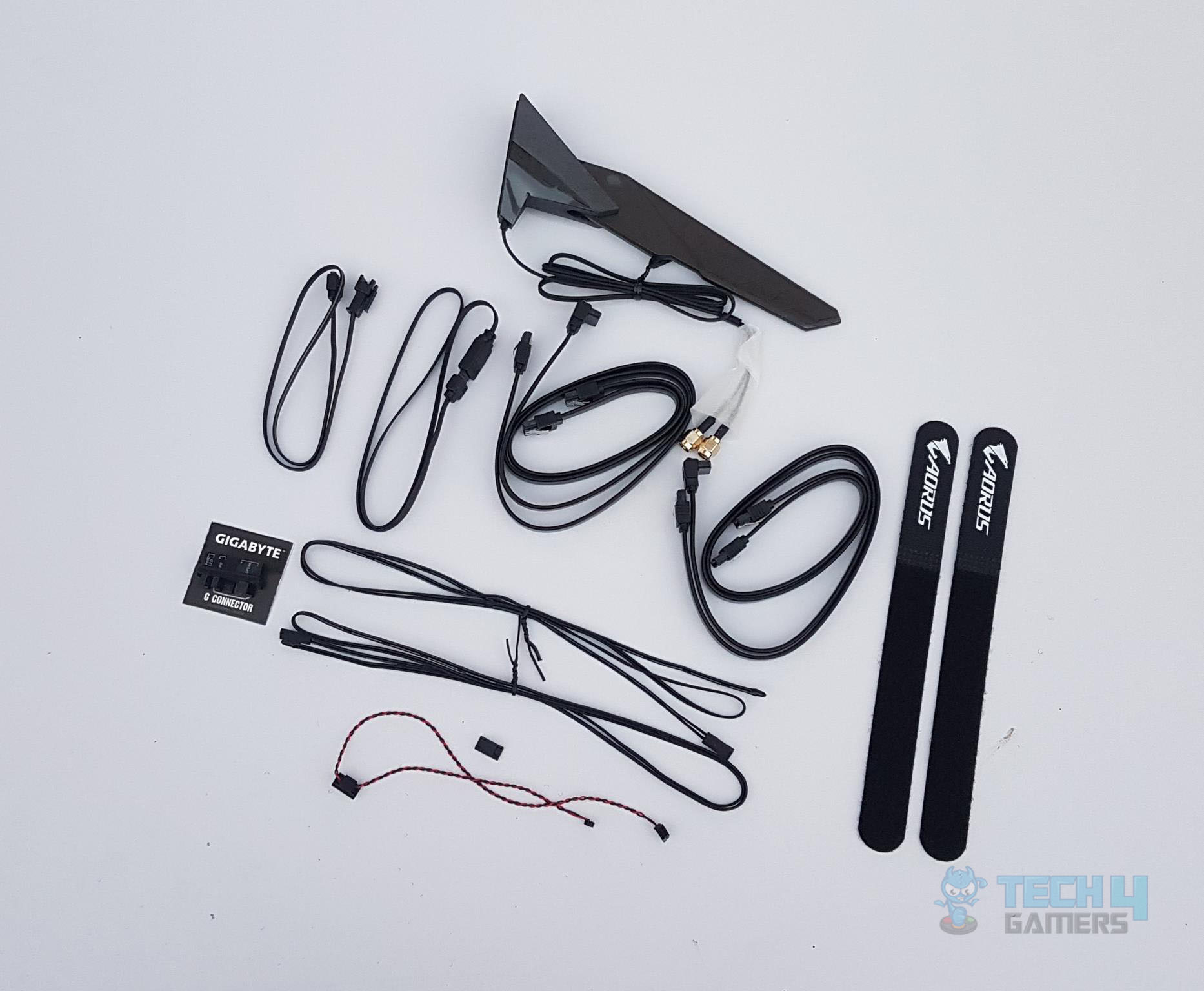
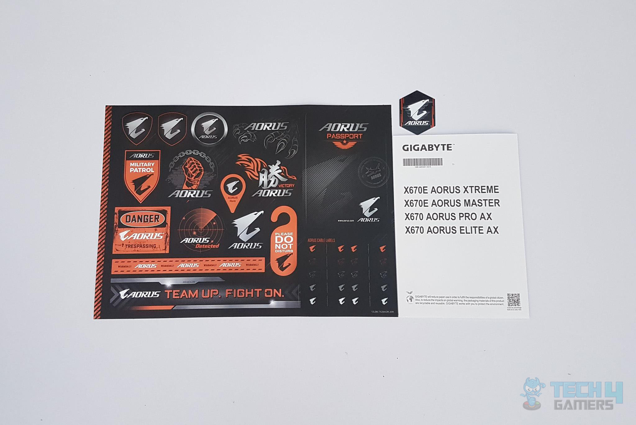
Accessories include:
- 1x Motherboard
- 1x WiFi Antenna
- 4x SATA Cables
- 1x Noise Detector Cable
- 2x AORUS Branded Velcro Strips
- 1x Front Panel G Connector
- 2x Thermistor Cables
- 1x RGB Extension Cable
- 1x RGB Cable
- 1x Case Badge
- 1x Sticker Sheet
Design
The X670E AORUS MASTER motherboard is the second most high-end offer from GIGABYTE. The motherboard has E-ATX size and is feature-rich. GIGABYTE has retained the stenciling and design elements from the previous generation; however, at the same time, they have gone to another level in the design department of the motherboard to deliver a solid product for the enthusiasts. Let’s start exploring the motherboard.
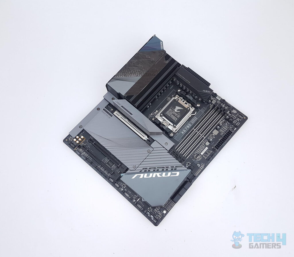
Taking a glance at the motherboard, we see a black PCB with gray stenciling. The heatsinks have a gray color tone, though the picture shows them to be silverish. The I/O cover has A-RGB elements and the chipset cover also features the A-RGB element. So, the RGB Fusion 2.0 is in play for the user on this motherboard.
One key note from a quick look is the beefy cooling solution on the VRMs and the Gen5 M.2 port. The rest of the three M.2 ports are covered. The complete chipset area is also covered. This gives the motherboard a clean and elegant look.
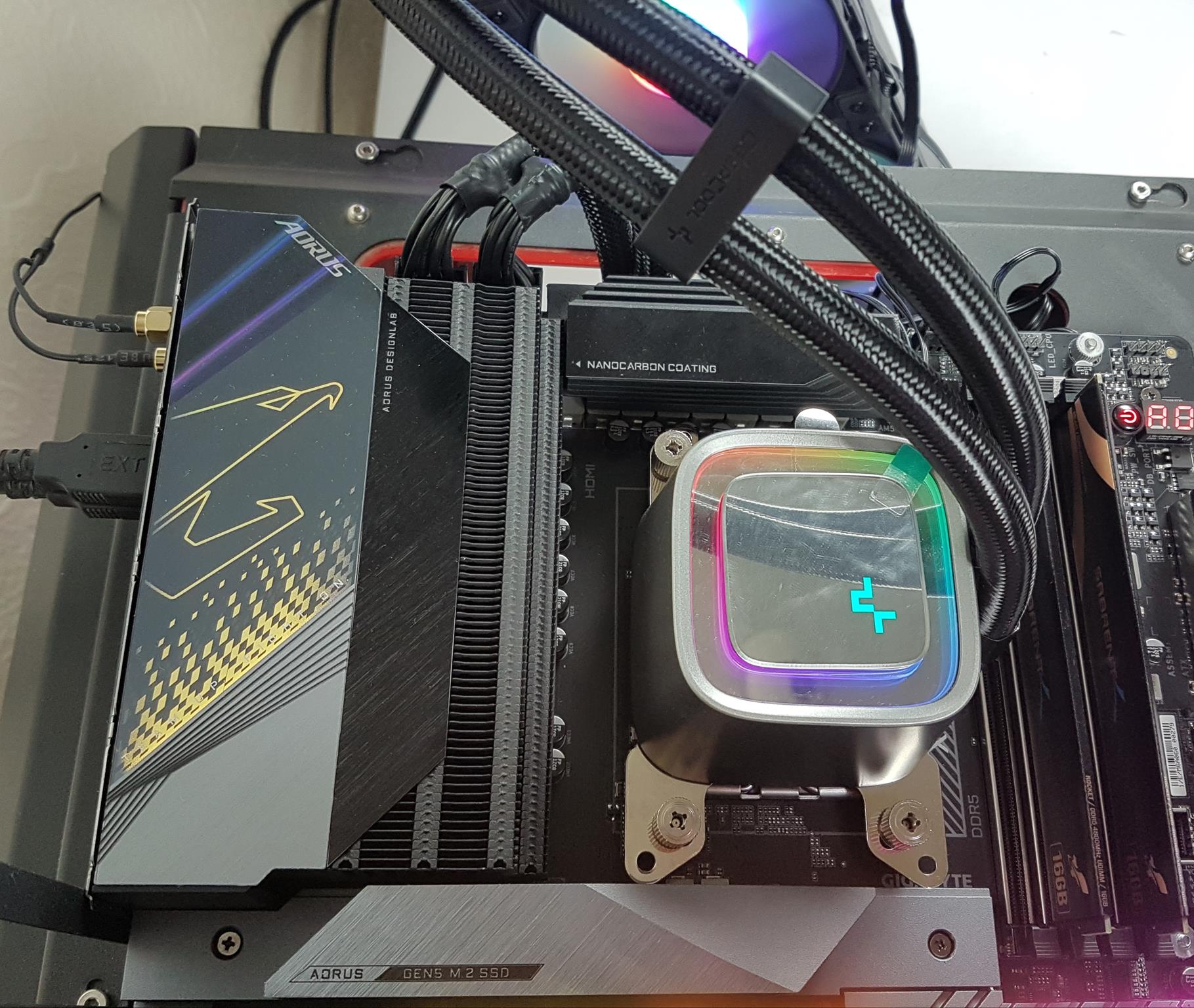
CPU Socket, Heatsink, VRM, And Power Delivery
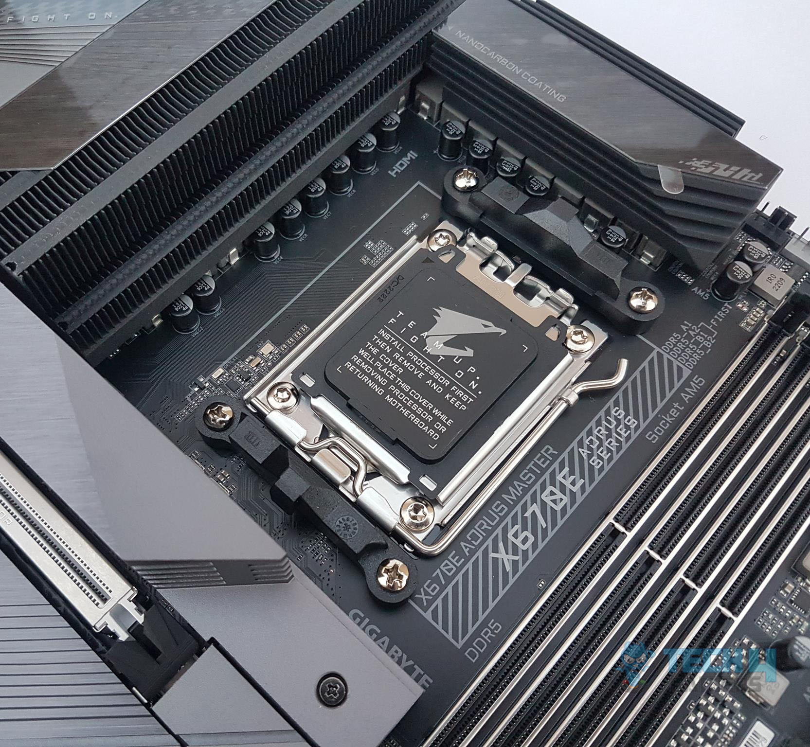
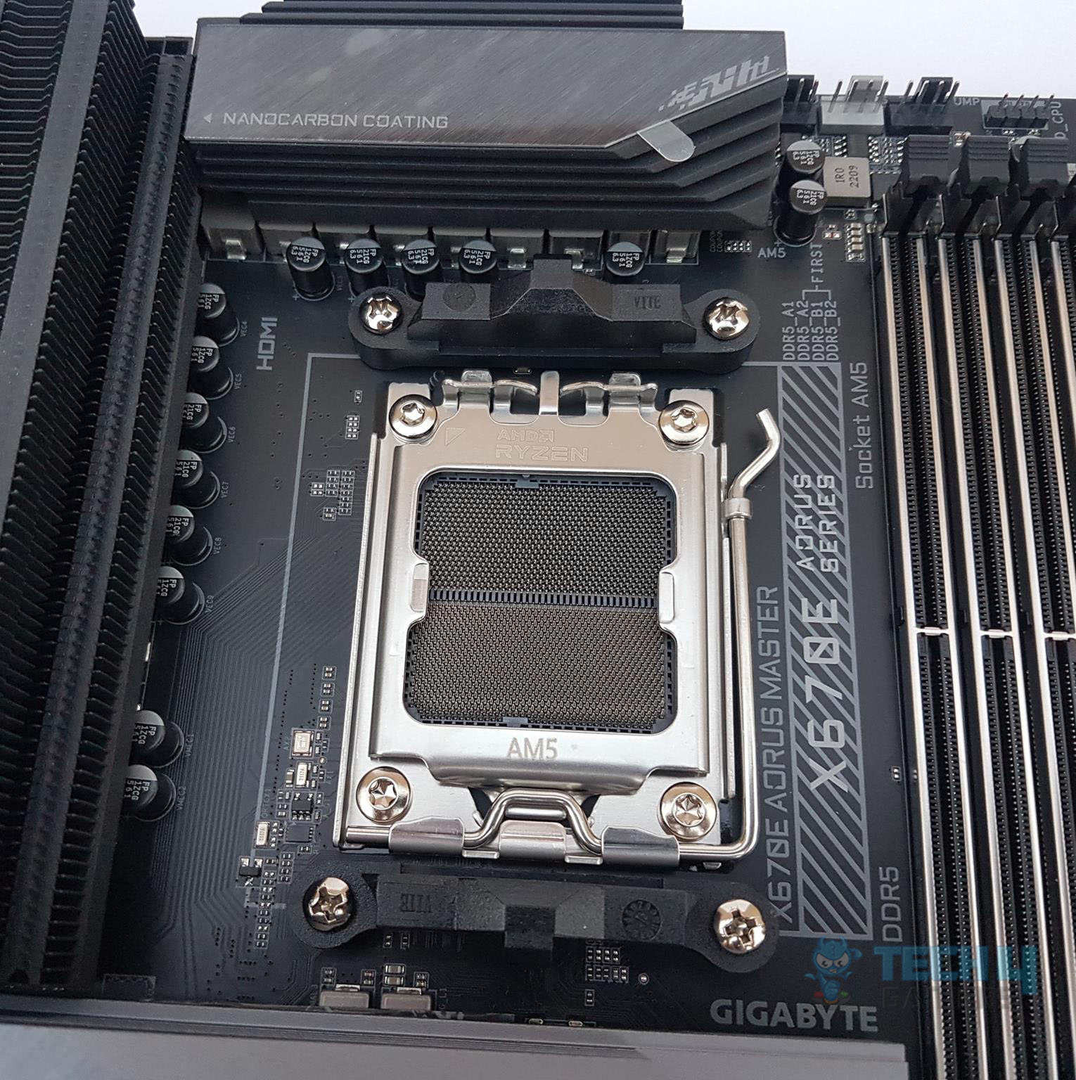
The X670E AORUS MASTER motherboard features a new socket from AMD named AM5. It is named as LGA 1718 as AMD has resorted to Land Grid Array (LGA). The previous generation of Ryzen series CPUs is not compatible with this socket. This is a flip-chip design supporting new 7000 series CPUs and DDR5 memory modules. There is a protective cover over the socket area.
The above picture shows the socket after removing the protective cover. The socket looks segmented into two. Take note of the brackets on the top and at the bottom of the socket. They are the same design as we have seen on the previous generation AM4 sockets.
Since the socket size is the same, any cooler compatible with the socket AM4 can be installed on the AM5 as well. AMD in this way has provided a good solution for the customer as they would not need to upgrade or change the cooling solution for the new socket.
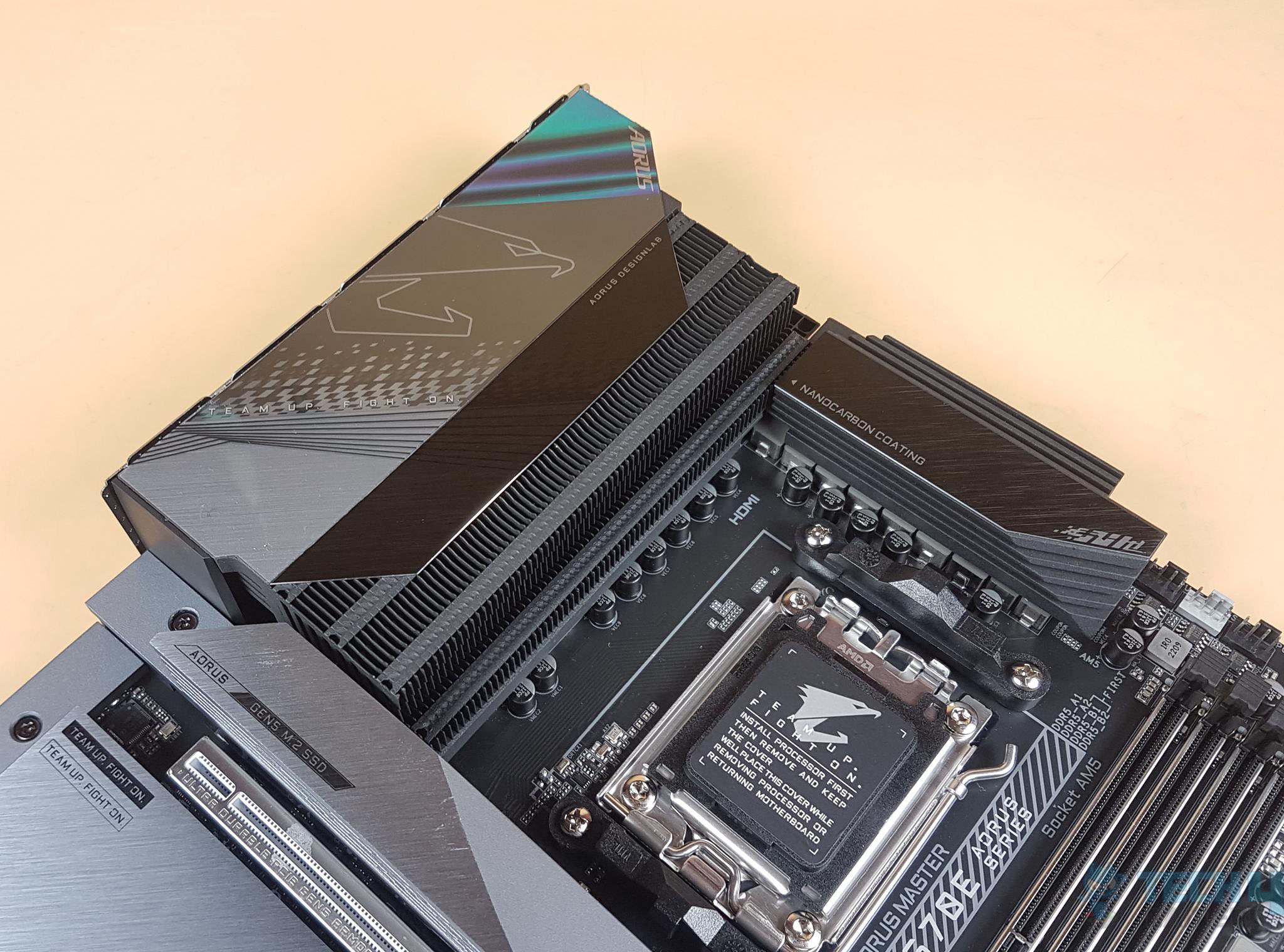
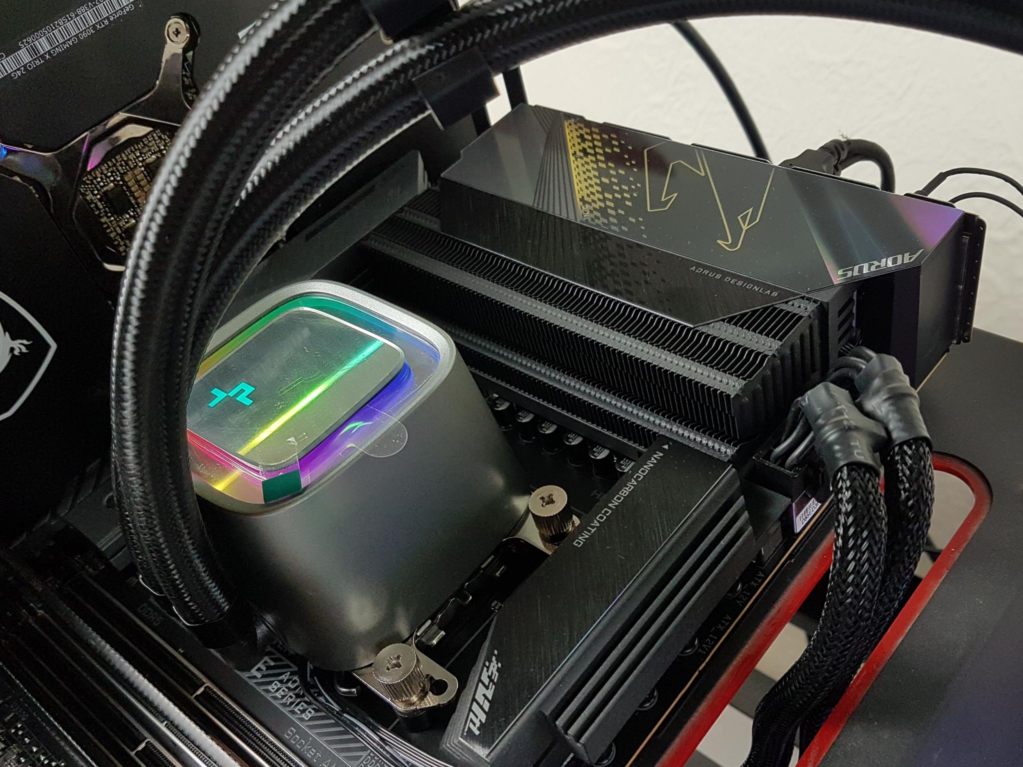
From a cooling perspective, GIGABYTE has implemented an effective solution. The I/O cover has an A-RGB backlit top with AROUS branding. There is a massive heatsink underneath the I/O cover. Both heatsinks are connected using an 8mm thick copper heat pipe. 8mm Mega-Heatpipe has a 30% wider diameter than the traditional 6mm heatpipe and is able to transfer more heat in the same time period. These heatsinks have a Nano-carbon coating, which according to GIGABYTE, enhances the heat transfer.
The nanocarbon particles are coated onto the heatsink through electrostatic adhesion. The coating material covers the entire finned heatsink with 200μm in thickness. In that way, heat is dissipated more quickly.
The above picture shows the beefy heatsink over the VRM and MOSFET. GIGABYTE has given due consideration to this department.
Since we are at it, let’s take a look at the power delivery of the motherboard.
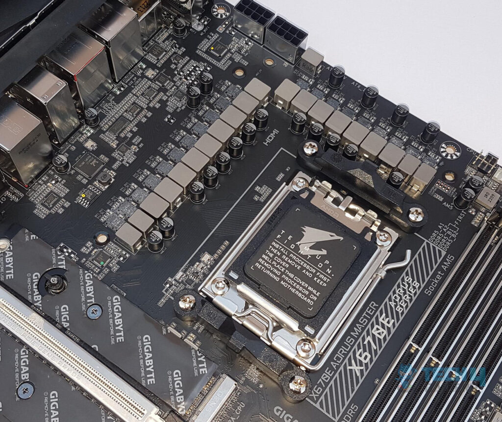
The X670E AORUS MASTER motherboard has beefy digital power phases. There are 16 phases in parallel (not direct) for the VCore using Renesas RAA2201054 SPS 105A making it 1680A. Then there are 2x MOSFETs for SOC using Renesas ISL99390 SPS 90A with a total of 180A for SOC for stable power delivery to the iGPU. Lastly, we have 2x MOSFETS for MISC using Renesas ISL99390 SPS 90A making it a total of 180A for stable power delivery to the PCIe lanes.
In terms of power delivery, this motherboard seems quite beefy though twin digital 16 phases sound like a doubler design to me. In comparison, the X670E AORUS Extreme has 20 direct phases with a better VRM PWM controller.
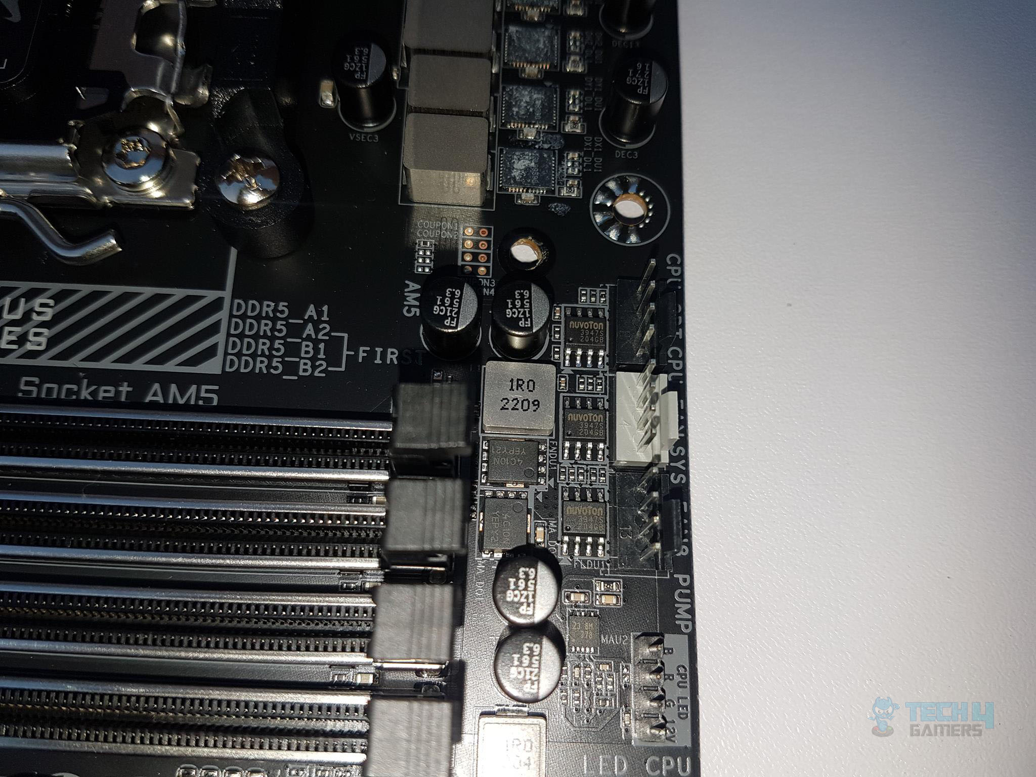
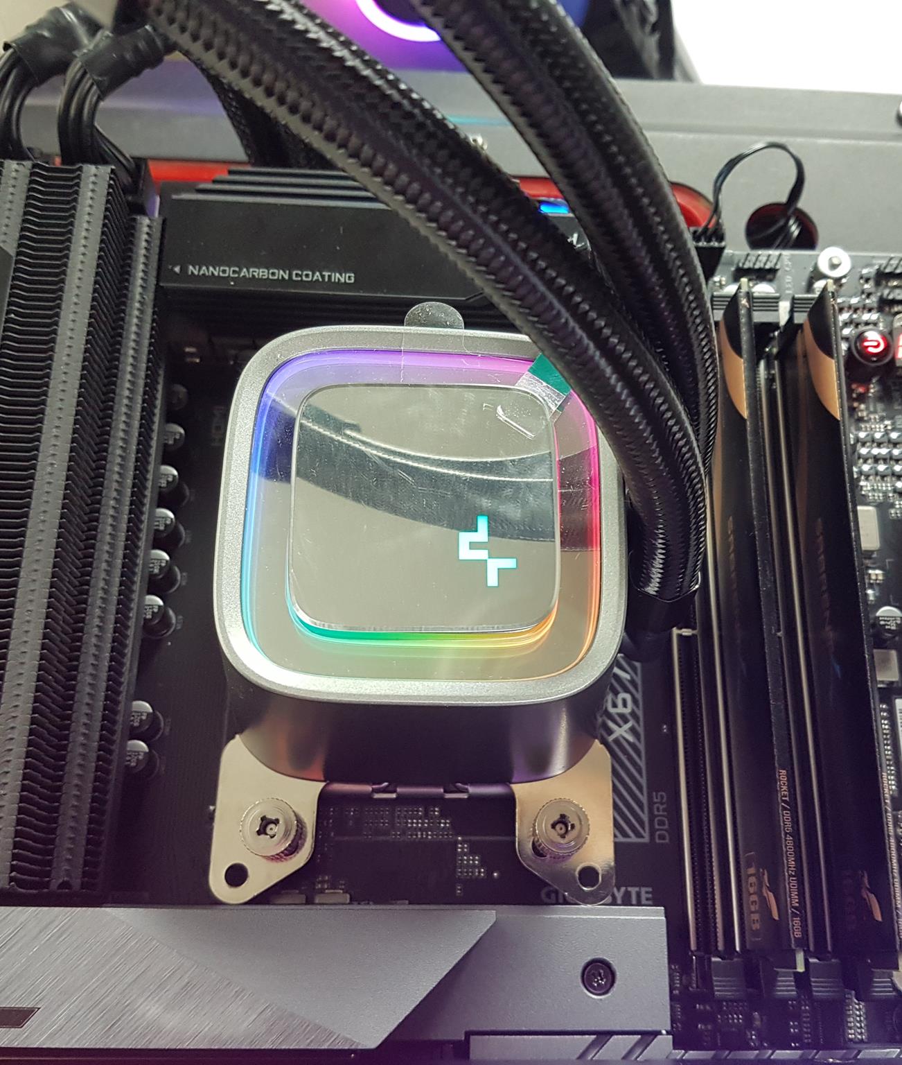
DIMM Slots
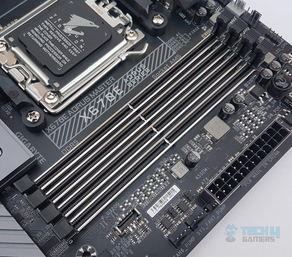
The X670E AORUS MASTER motherboard has 4x DDR5-based DIMM slots, which are reinforced with SMD stainless steel. There is anti-plate bending support of up to 130% and these slots support plug/unplug time 5000 times. The DDR5 up to 5200MHz is supported (with BIOS update). By default, the board supports 4400 and 4800MHz. A total of up to 128GB RAM capacity is supported with a single stick density of 32GB. This is Dual Channel architecture and supports un-buffered DIMM 1Rx8/2Rx8/1Rx16 memory modules.
This board supports AMD EXPO and Intel XMP profiles. EXPO stands for the Extended Profiles for Overclocking. GIGABYTE AM5 MB supports both AMD EXPO and Intel XMP overclocking memory modules for maximal compatibility. MB will automatically detect both profiles format in SPD, users can choose to enable one of the profiles from the BIOS menu and easily reach overclocked memory performance.
M.2 Ports and Thermal Guard III
One of the salient features of AMD’s new platform is the support for upcoming Gen 5 base M.2 NVMe SSDs and we are seeing some jaw-dropping read/write speeds on those drives. The X670E chipset provides support of Gen 5 for the PCIe slot and M.2 port, unlike the X670 chipset. The X670E AOURS MASTER is providing the same support but taking the game to the next level by giving two M.2 ports on the Gen 5 bus along with a fully slotted x16 PCIe slot.
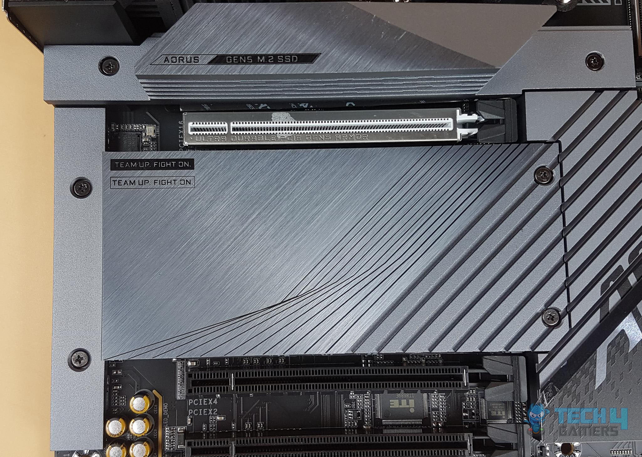
This motherboard has a total of 4x M.2 ports. Two of these ports are wired directly to the CPU socket whereas the two are wired to the second PROM21 chipset. We have got some stylish M.2 covers for these ports.
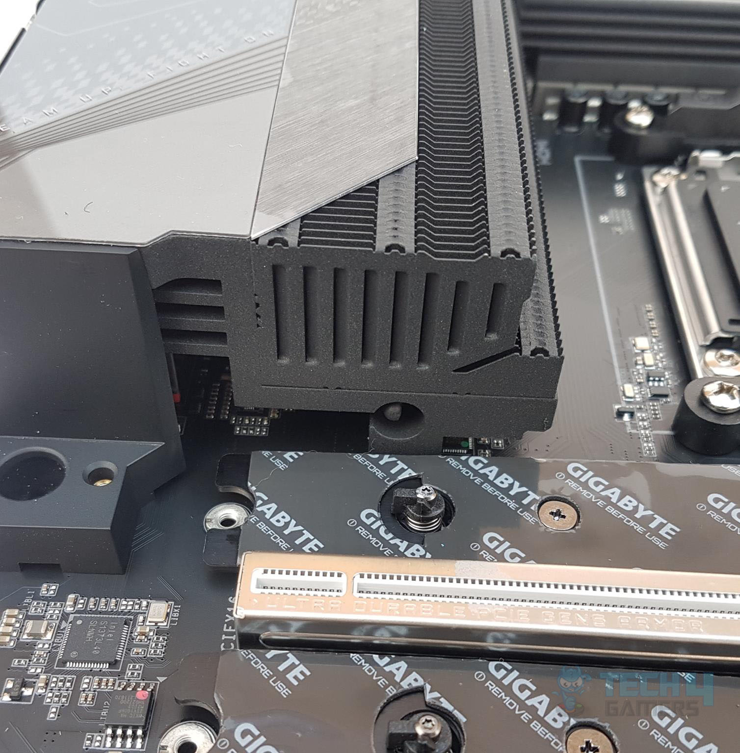
The topmost slot has a layered heatsink with a thermal pad underneath for efficient heat transfer. GEN5 M.2 SSD is written on the cover. This cover is separated from the other covers. It can be taken off by unscrewing the 2x Philips screws.
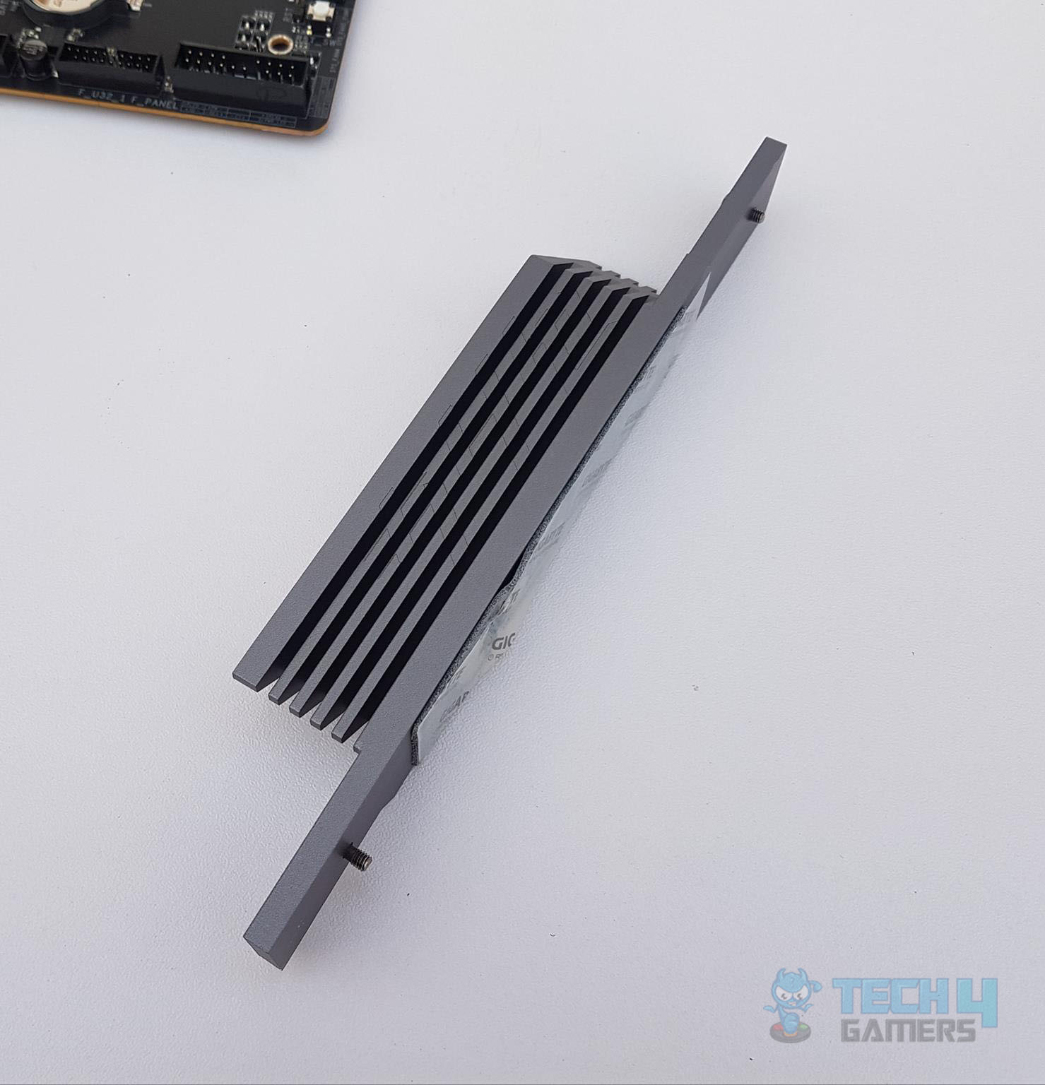
The above picture shows the cover removed from the motherboard. Look at the layered design of the aluminum-made heatsink. M.2 Thermal Guard III is constructed with a 9X optimized heat dissipation surface to prevent throttling and bottleneck that high-speed/ large capacity of PCIe 5.0 M.2 SSDs may cause, especially under a heavy workload. The special design of heatsink grooves in the direction of the CPU further enhances the in-chassis air flow and optimizes the heat convection efficiency.
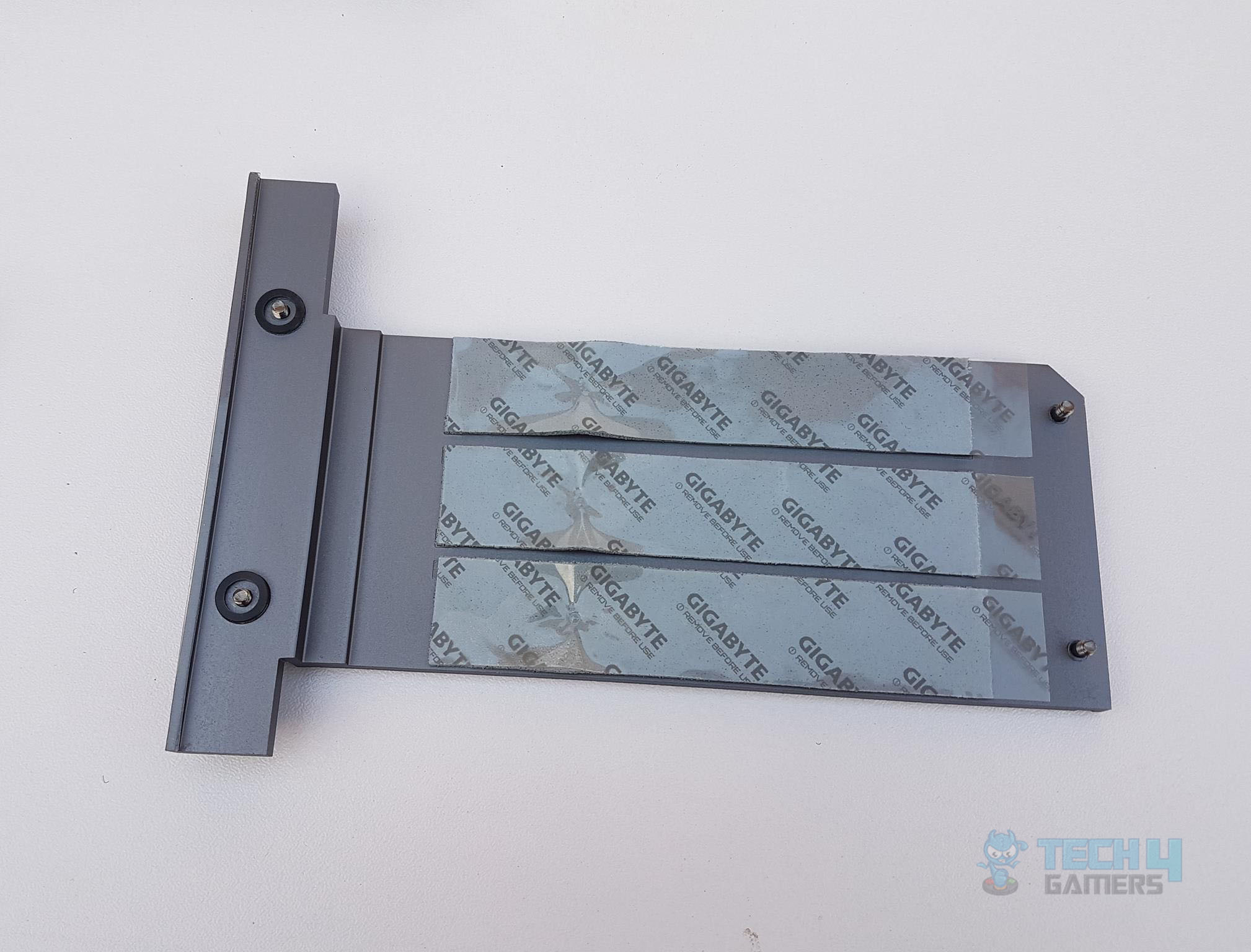
GIGABYTE has taken the game to the next level by incorporating dual-sided thermal pads for dual-sided populated M.2 SSDs.
The above picture shows the large NVMe cover removed from the motherboard. Take note of 3x thermal pads on the inner side of the cover. This cover is secured using 4x Philips screws.
PCIe Slots and EZ-Latch Plus Design
Now, let’s focus on the PCIe slots on this motherboard. This motherboard has 3x PCIe slots.
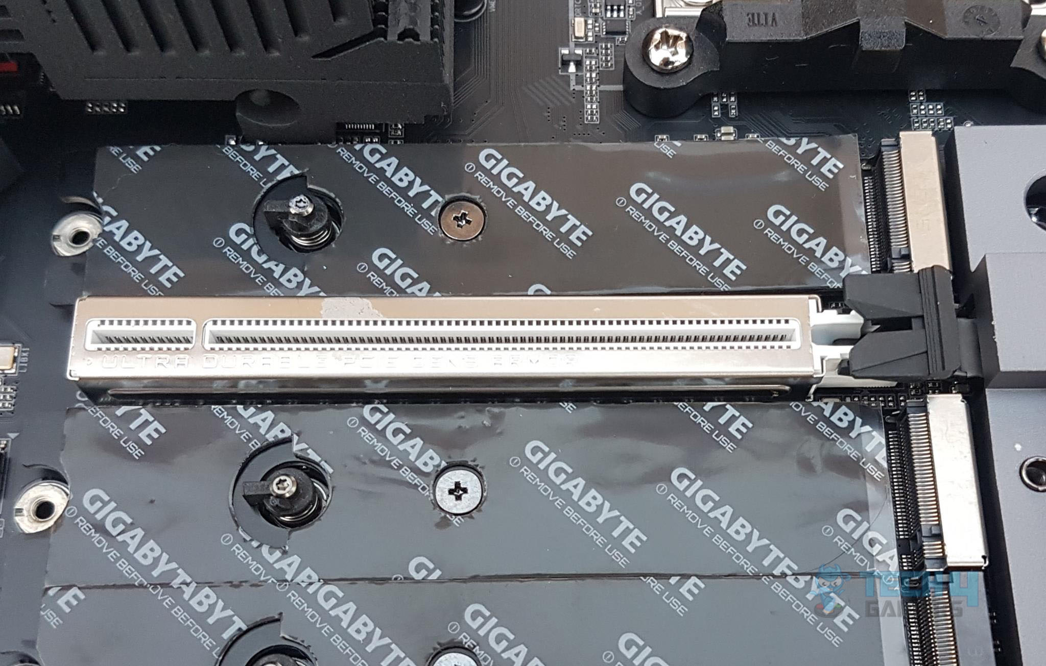
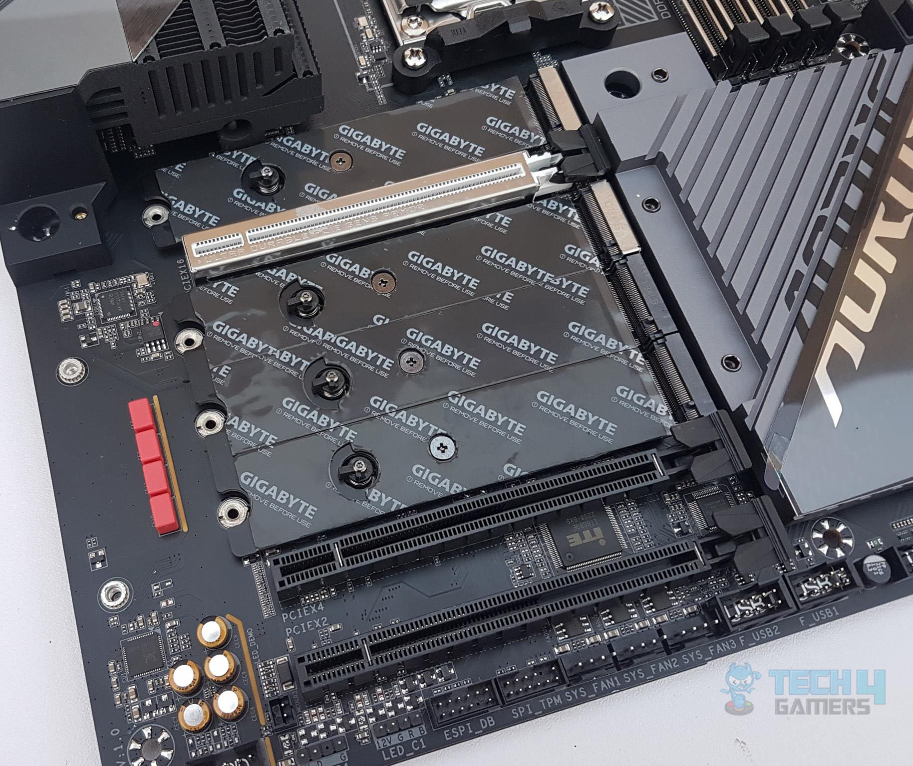
The topmost PCIe slot is wired to the CPU socket and is a fully functional PCIe Gen 5 slot with a theoretical bandwidth of 128GB/s. This slot is SMD stainless-steel reinforced. This Ultra-Durable SMD PCIe 5.0 Armor Stainless-steel PCI-e Shielding becomes 20% wider providing reinforced tensile strength. As we have seen on the previous GIGABYTE motherboards, this motherboard is using double locking bracket for the topmost slot.
The second PCIe slot PCIe 4.0 rated at x4 speed and the last slot is PCIe 3.0 rated at x2 speed which could be a let-down for the users. This motherboard supports AMD Cross-fire on PCIe x16 and PCIe x4 slots. The very reason that the last PCIe slot is rated for X2 speed is that the single PCIe 3.0 bus is shared with this port, 2x SATA ports, and Intel LAN and Wi-Fi connectivity. Also, it is pertinent to mention that there is a switch managing the last PCIe slot with the two SATA ports (4 and 5). At one time either of them will be active or enabled. This is kinda too restricted on this high-end motherboard.
GIGABYTE has implemented what they called PCIe EZ-Latch Plus. There is a button above the chipset cover. Pressing it will release the graphics card from the first PCIe (Gen 5) slot. This is a convenient mechanism to release the graphics card. There is a tight space to access the locker on the slot itself. Plus this would also help in preventing the accidental breaking of the slot locker.
X670E Chipset
Now, it is time to take a look at the X670 chipset area.
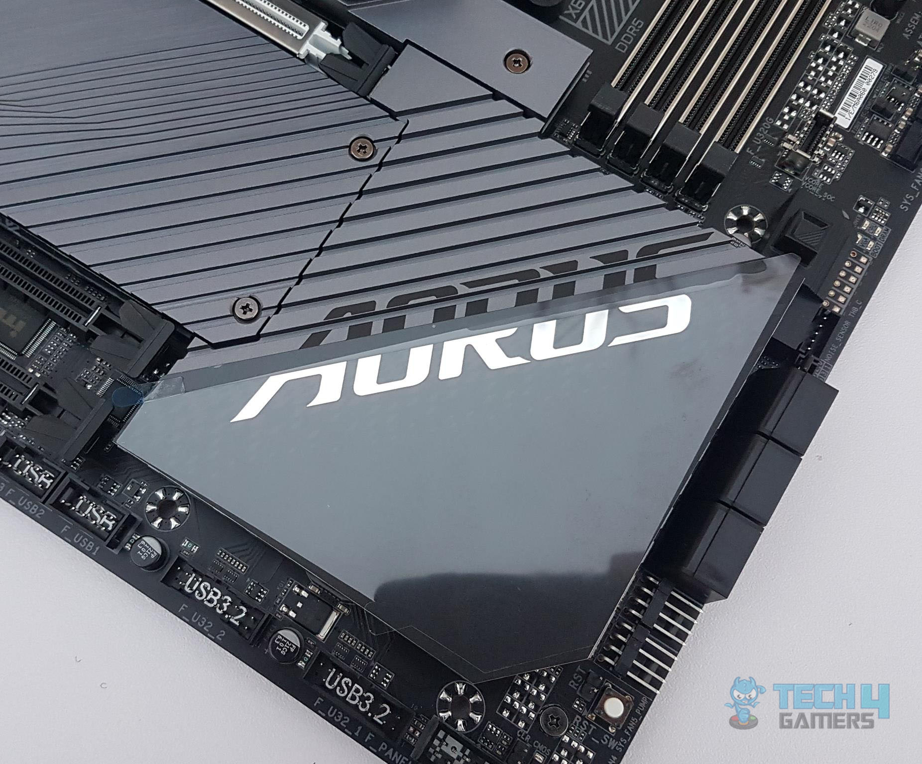
There is a large size solid aluminum cover over the Chipsets area with stylish AORUS branding and gray and black colors combination. This cover syncs with the NVMe covers in the overall layout for some elegant outlook on the motherboard. There are 4x screws on the backside of the PCB. Removing them will release the cover.
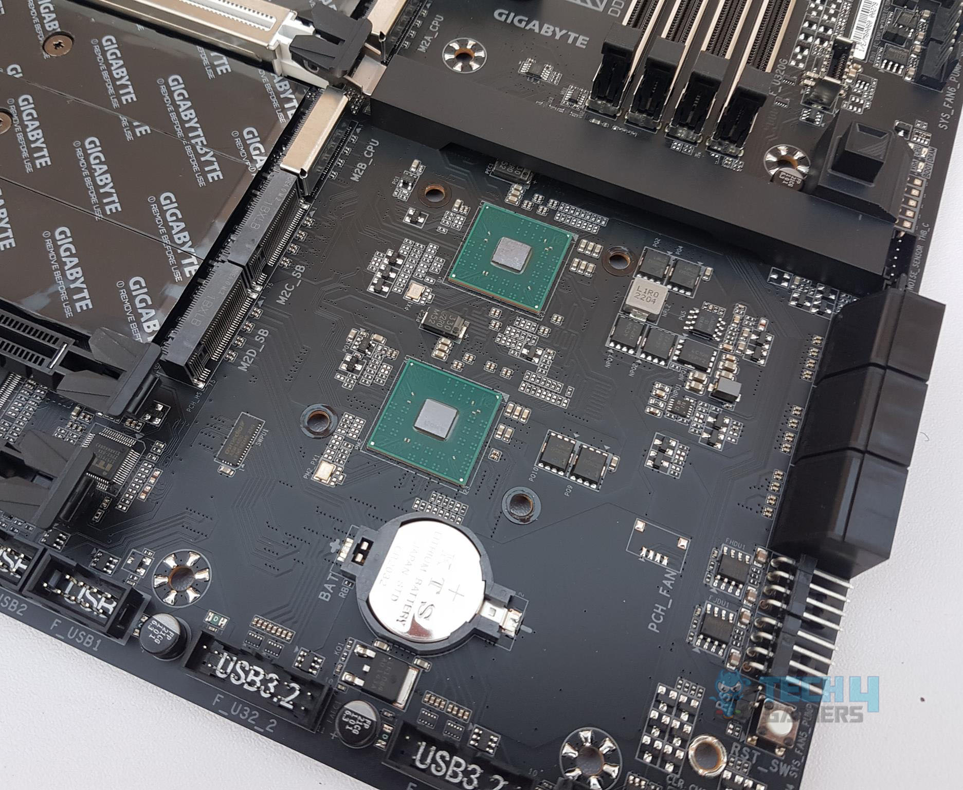
The above picture shows the underside of the chipset cover. In case you are wondering, what are those 3 mounting holes? These are there for the backplate screws. We will come to that later.
We have mentioned in the introduction that AMD has opted for two chipsets in daisy-chain connection. We can see the two chipsets here. The CMOS battery is also located in this area which would mean the CMOS battery is covered as well. This is not a convenient design at all. In order to access this battery, we will need to remove the graphics card first as it sits over the chipset main cover and then access the backside 4 screws for which the backplate would need to be removed as well. And to all this, you would need to remove the motherboard from the PC Case.
Anyhow, the use of two chipsets with each taking 7W power enabled the GIGABYTE and AMD to go for the passive cooling over the chipset. If you remember, we have active cooling on the X570 chipset. So, this is a good comeback from team red.
Audio Solution
This motherboard is using RealTek ALC1220-VB codec to drive the audio solution. This is an ok solution that could have been better but you may eye the X670E AORUS EXTREME motherboard.
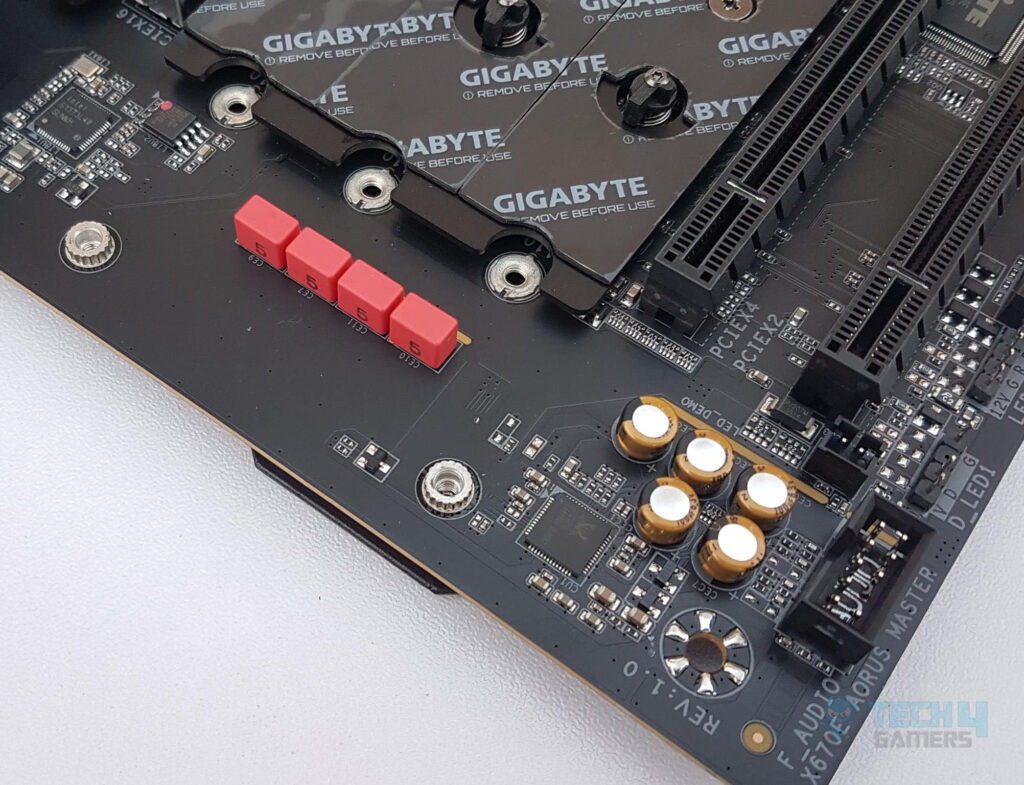
The above picture shows the well-shielded Audio circuitry. We have high-end WIMA and Fine-Gold capacitors to drive the power of the circuit. This ensures a studio-quality experience. This is a Hi-Res Audio certified solution, meaning that the product is capable of reproducing frequencies up to 40kHz or above which ensures users with the best audio quality at all times.
Please note that the back panel line out port supports DSD audio. Though we have two ports on the back panel, the user can use the audio software to configure the 7.1-channel output. There is also support for 2/4 and 5.1 channel output.
Networking Connectivity
We have two main areas here:
- Wireless connectivity
- Wi-Fi
- Bluetooth
- Wired connectivity
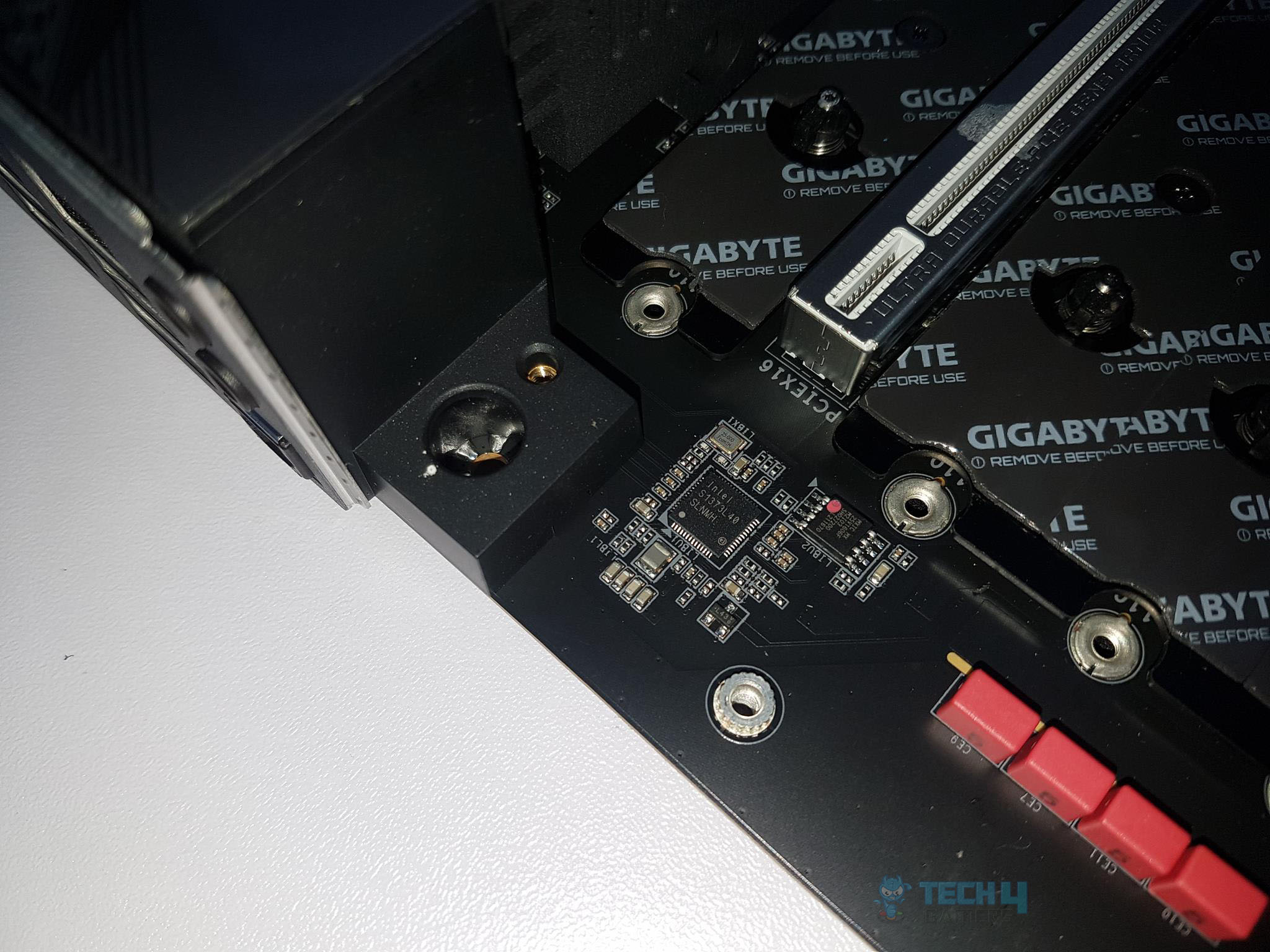
GIGABYTE has provided a single 2.5GbE LAN chip using Intel S1373L. I was expecting 10GbE connectivity but that is provided in the X670E AORUS EXTREME. There is a single RJ-45 port on the back panel for the wired network connectivity. Still, 2.5GbE provide roughly double the speed of that 1GbE connectivity. good online gaming experience. The Ethernet port supports 10/100/1000/2500Mbps.
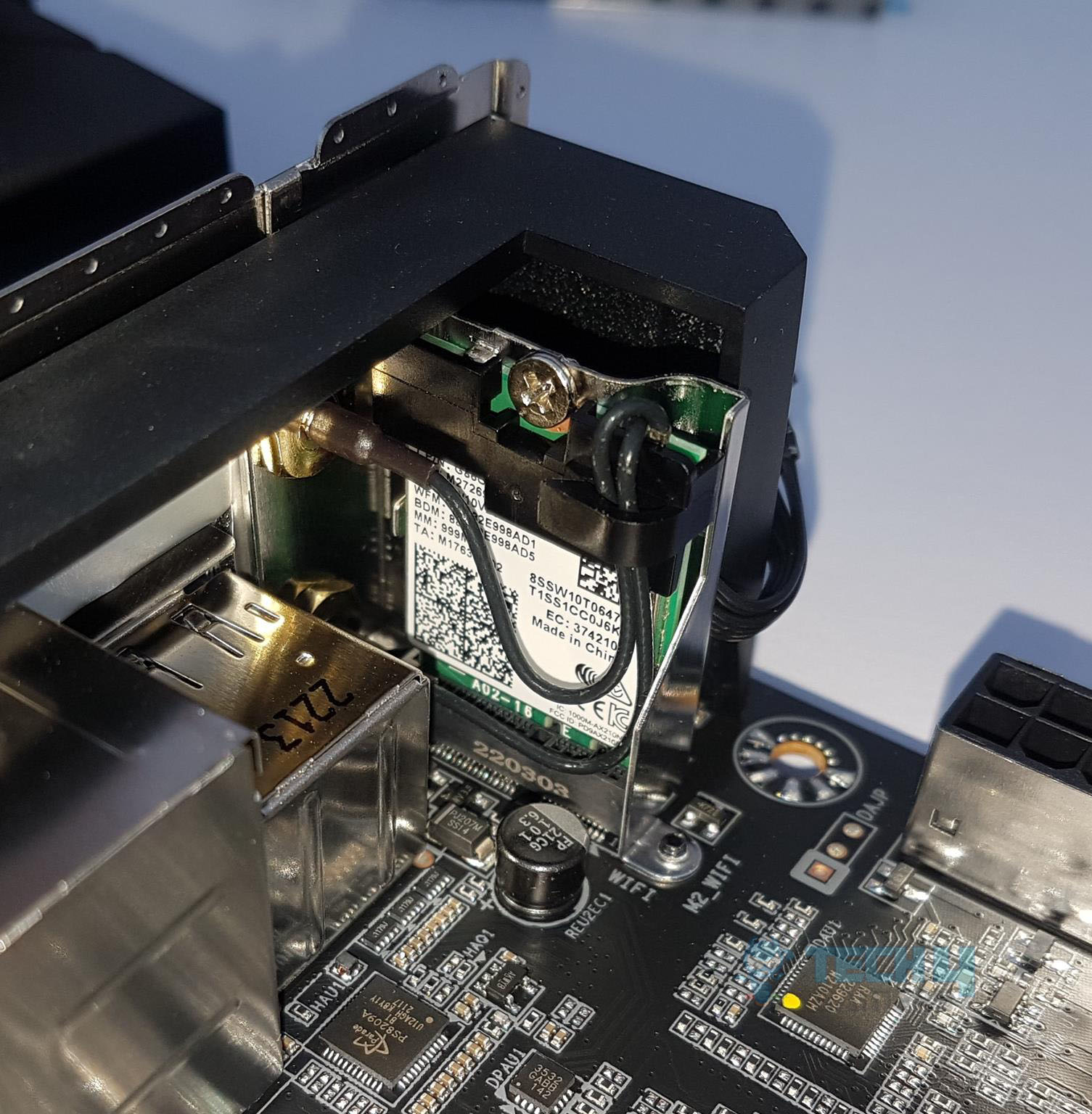
The Intel Wi-Fi module is implemented on the mSATA NGGF port on the rear I/O panel. The main driving force is the Intel AX210 chip capable of Wi-Fi 6E connectivity. The latest Wireless solution 802.11ax Wi-Fi 6E with a new dedicated 6GHz band enables gigabit wireless performance provides smooth video streaming, a better gaming experience, lesser dropped connections, and speeds up to 2.4Gbps. The motherboard features Bluetooth 5.3 protocol.
Some of the key benefits of Wi-Fi 6E compared to Wi-Fi 5 are:
- 40% faster speed for a smoother gaming/streaming experience
- 50% higher resolution for video game-related content
- Better battery life for VR devices
Spectrum congestion is a huge problem in the current Wi-Fi environment nowadays because too many devices all use the existing 2.4GHz and 5GHz spectrum, and it causes unreliable connection and slower speed. Wi-Fi 6E is an extended standard to Wi-Fi 6, and it uses a dedicated 6GHz band that provides not only a brand new frequency to transfer data but also a spacious spectrum for future devices. With Wi-Fi 6E, users can enjoy a faster connection and stronger signals than before.
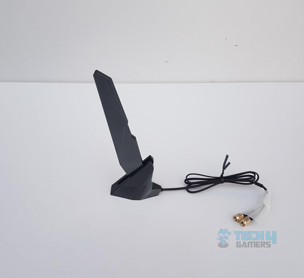
GIGABYTE has provided a Wi-Fi antenna in the box with a magnetic base for convenient mounting.
USB Connectivity
The X670E AORUS MASTER is taking full advantage of the dual chipset design of the X670E and the USB-rich CPU socket features. Resultantly, we have USB 3.2 Gen 2×2 Type-C ports on the front and the rear.
First, we take a look at USB connectivity from the CPU socket:
- 1 x USB Type-C® port on the back panel, with USB 3.2 Gen 2 support
- 2 x USB 3.2 Gen 2 Type-A ports (red) on the back panel
- CPU + USB 2.0 Hub: 2 x USB 2.0/1.1 ports on the back panel
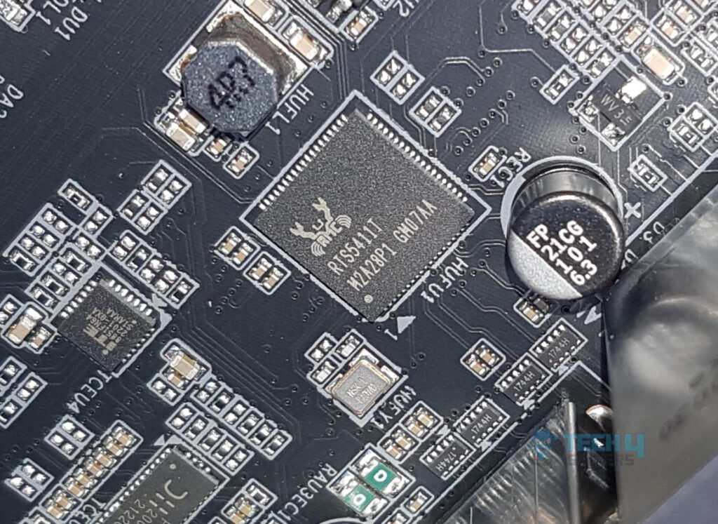
RTS5411 is an advanced USB3.0 4-port HUB controller, which integrates USB3.0 and USB2.0 Transceivers, MCU, SIE, regulator, and charger circuits into a single chip. RTS5411 is fully backward compatible with USB2.0 and USB1.1 specifications which can be operated in Super-Speed, High-Speed, Full-Speed, and Low-Speed.
Now, we take a look at the USB connectivity from the chipsets:
- 2 x USB Type-C® ports, with USB 3.2 Gen 2×2 support (1 port on the back panel, 1 port available through the internal USB header)
- 2 x USB 3.2 Gen 2 Type-A ports (red) on the back panel
- 4 x USB 3.2 Gen 1 ports are available through the internal USB headers
- 4 x USB 2.0/1.1 ports are available through the internal USB headers
- Chipset+USB 3.2 Gen 1 Hub: 4 x USB 3.2 Gen 1 ports on the back panel
We can see the plethora of USB connectivity options on this motherboard.
This board has USB 3.2 Gen 2×2 over a Type-C interface providing a theoretical bandwidth of 20Gbps. The rear USB 3.2 Gen 2 Type-C® provides DisplayPort™ Alternate Mode as well. DisplayPort™ over USB Type-C® enables the delivery of full DisplayPort A/V performance (driving monitor resolutions of 4K and beyond), SuperSpeed USB (USB 3.2 Gen 2) 10Gbps data transition, and power delivery with the convenience of reversible plug orientation and cable direction.
Internal And External Connectors
Now that we have covered the main features, functions, and design of the motherboard, let’s take a look at the internal connectors.
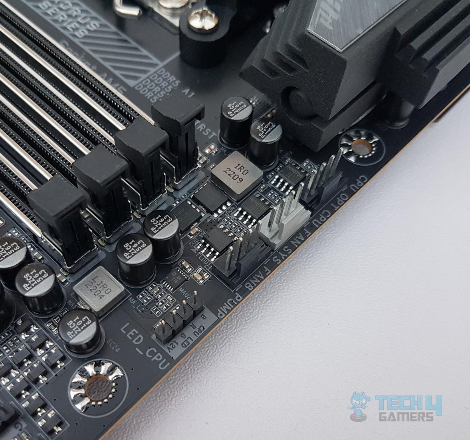
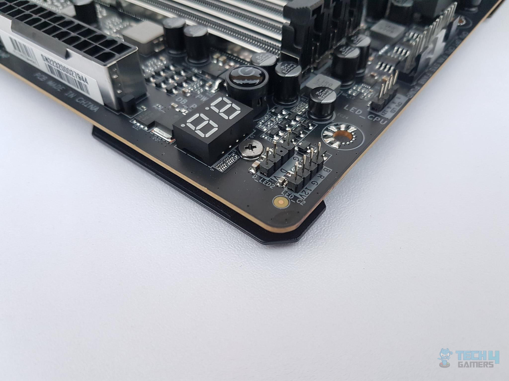
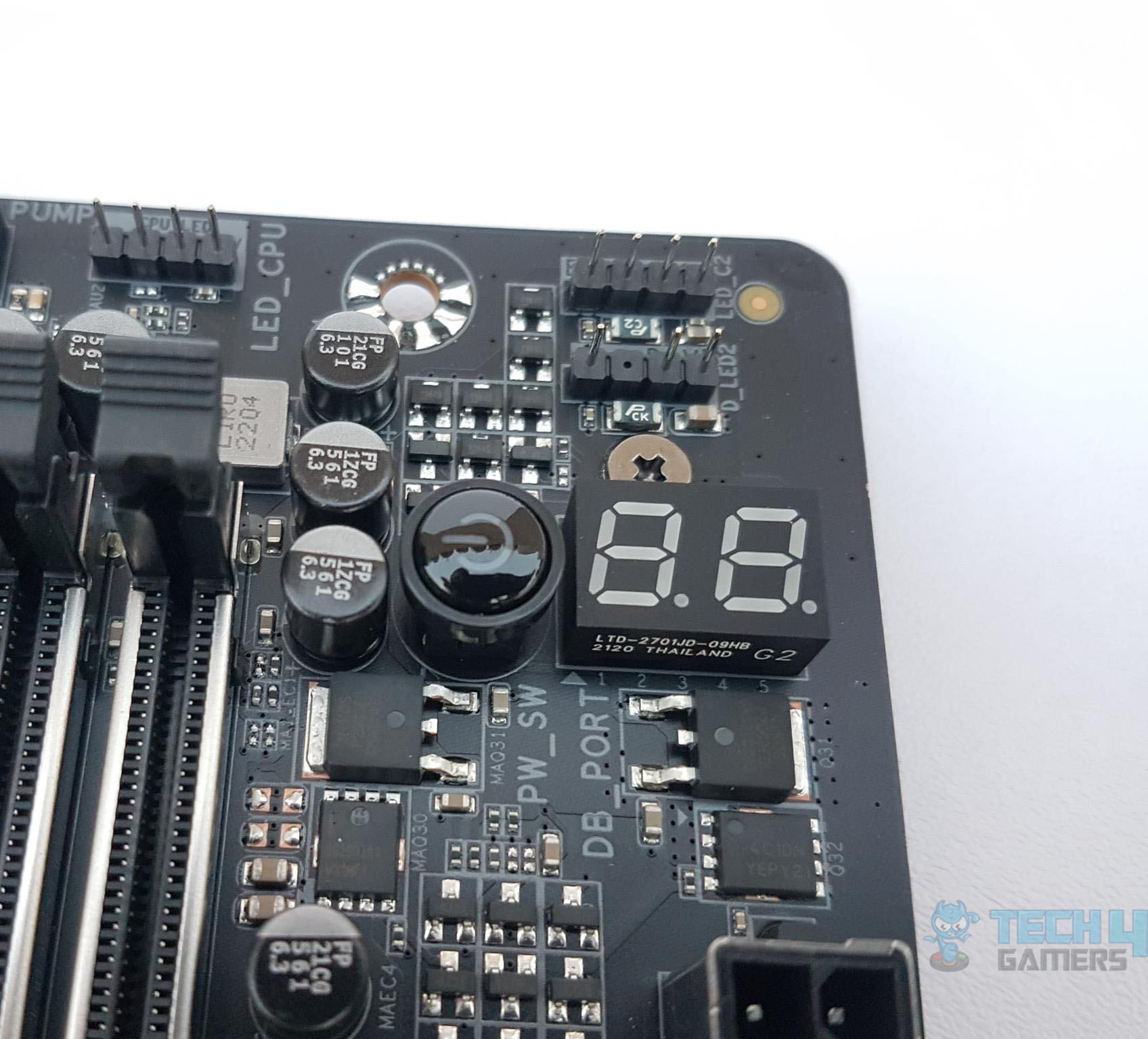
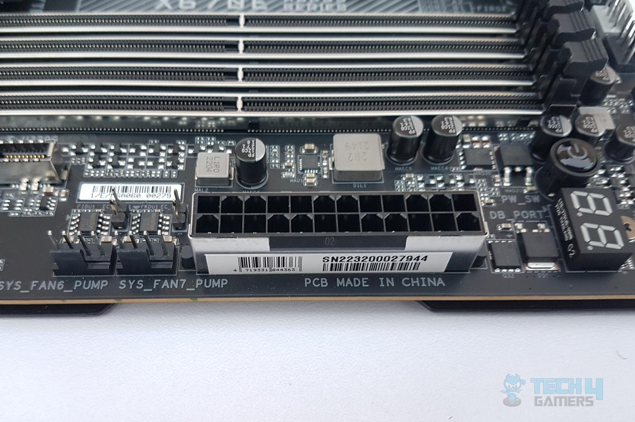
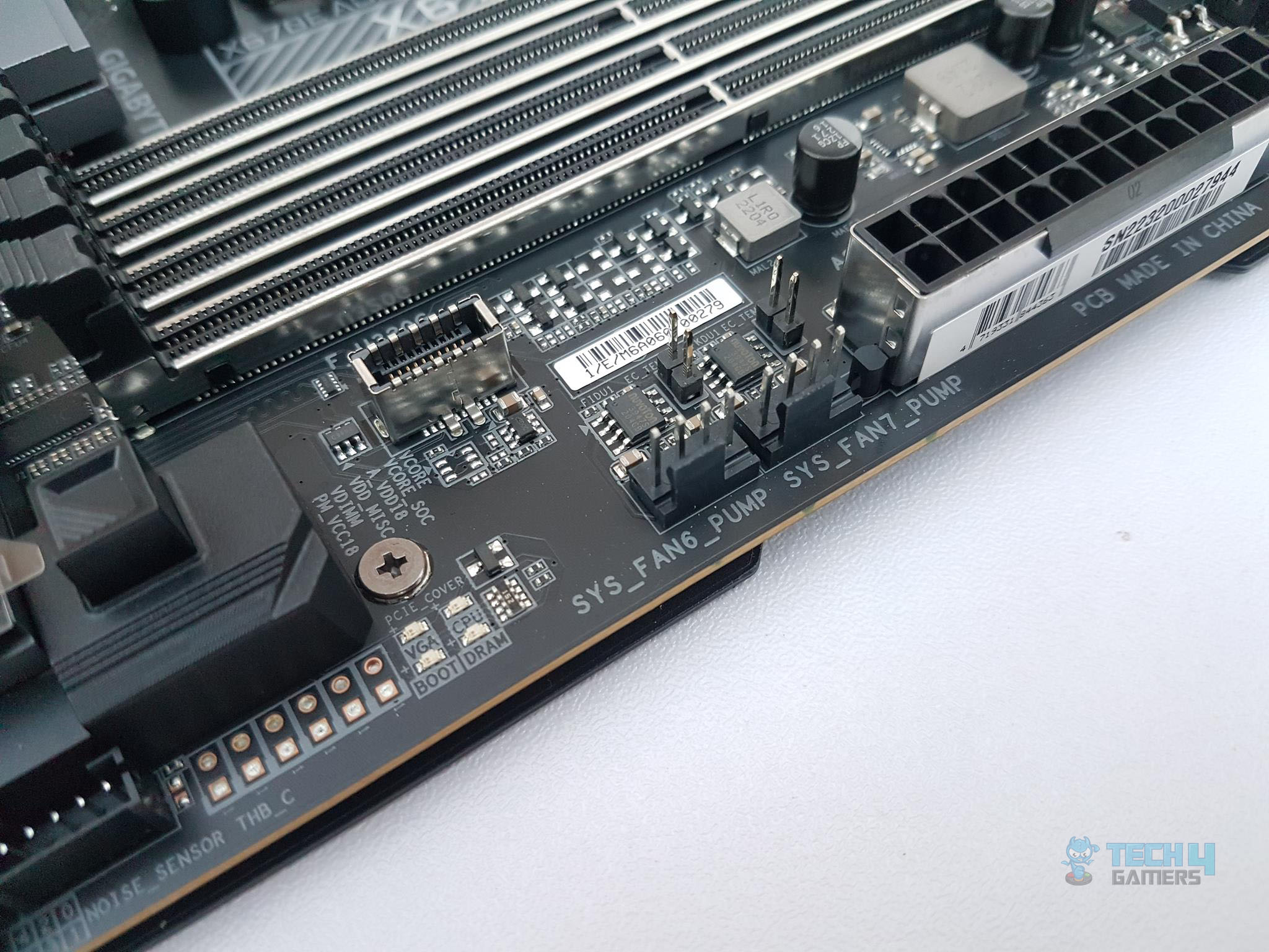
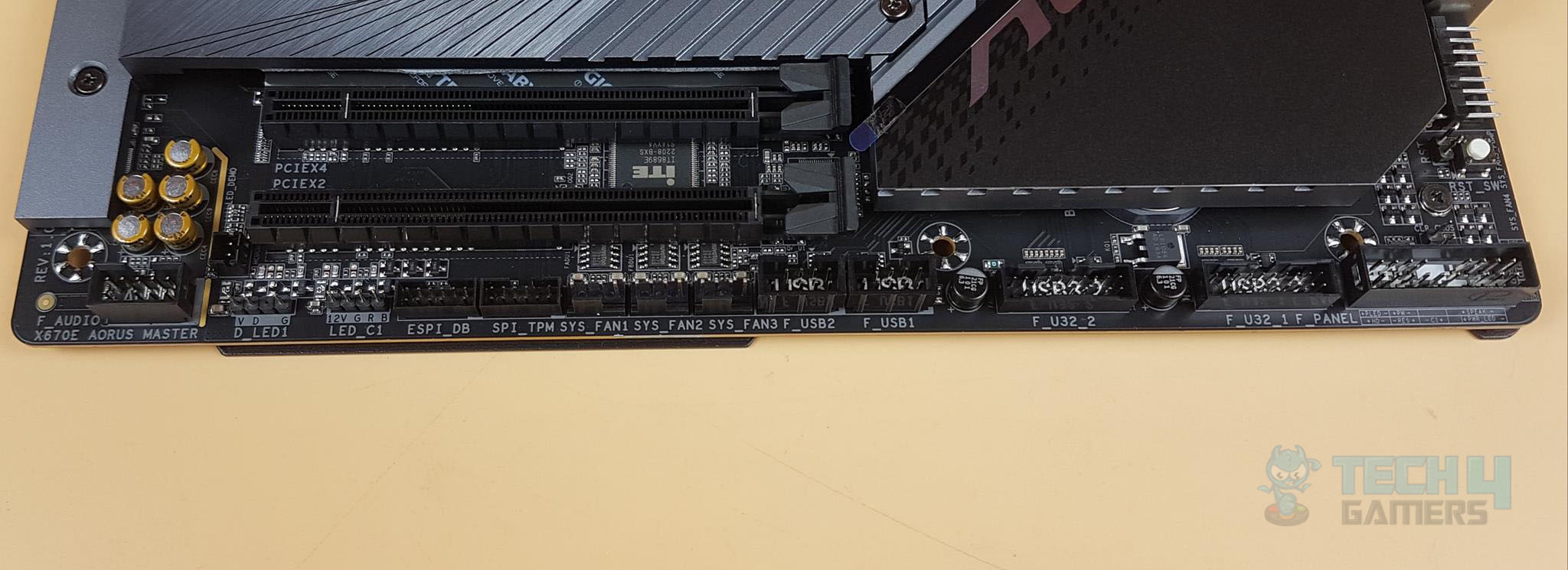
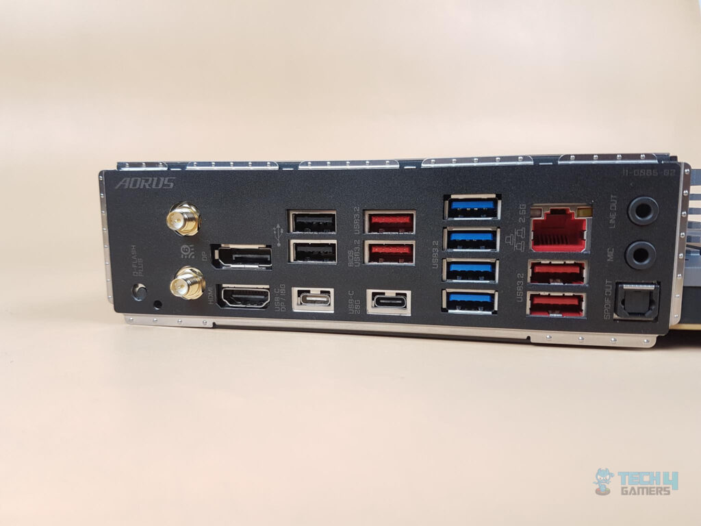
The following options are provided:
- 1 x Q-Flash Plus button
- 2 x SMA antenna connectors (2T2R)
- 1 x DisplayPort
- 1 x HDMI 2.0 port
- 1 x USB Type-C® port (DisplayPort), with USB 3.2 Gen 2 support
- 1 x USB Type-C® port, with USB 3.2 Gen 2×2 support
- 4 x USB 3.2 Gen 2 Type-A ports (red)
- 4 x USB 3.2 Gen 1 ports
- 2 x USB 2.0/1.1 ports
- 1 x RJ-45 port
- 1 x optical S/PDIF Out connector
- 2 x audio jacks
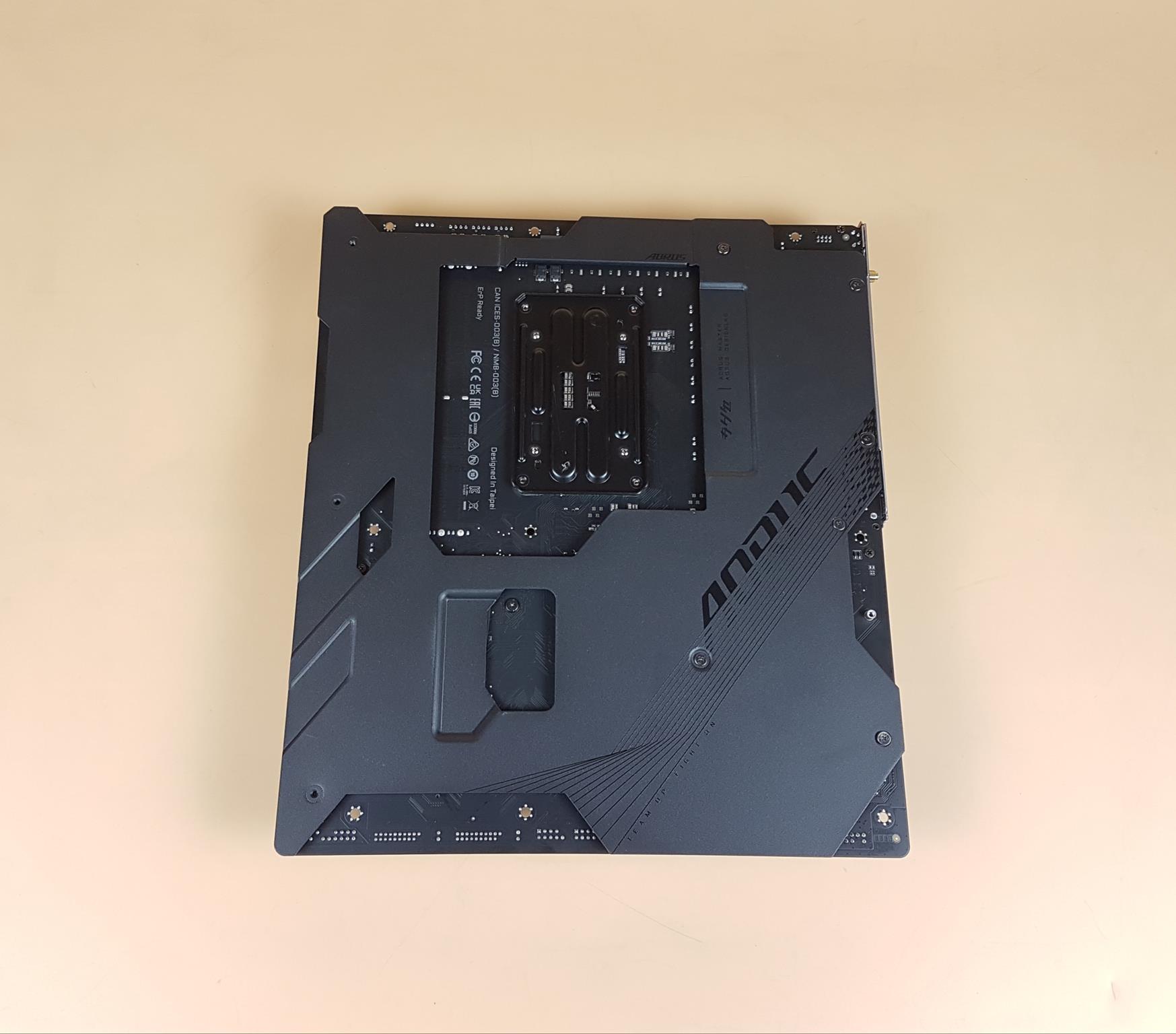
The above picture shows the backside view of the motherboard. There is a nanocarbon-based backplate on the motherboard. The backplate is in black color and it also helps in heat transfer. There is AORUS branding on it as well.
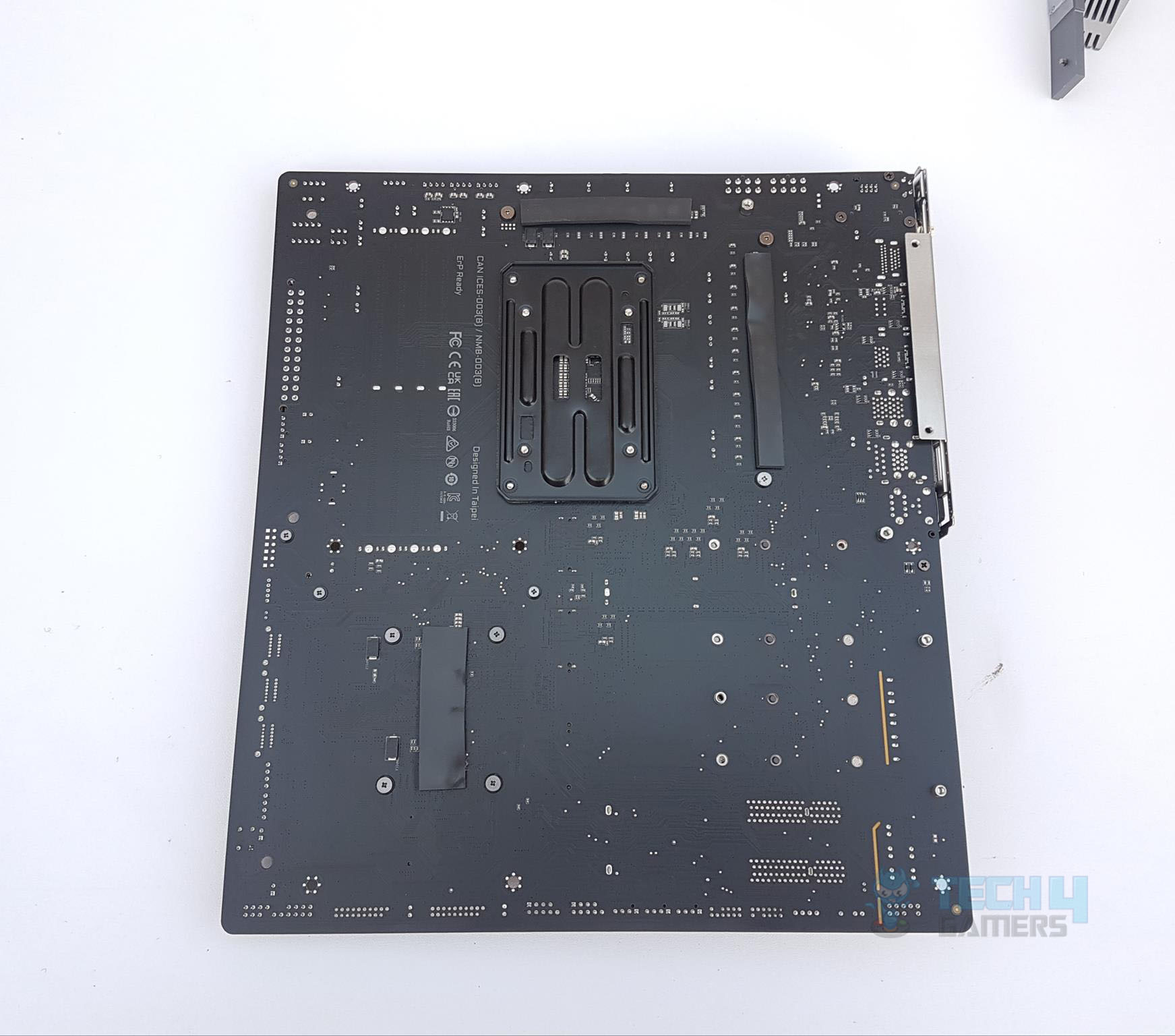
The above picture shows the backside view of the motherboard after removing the backplate. We can see three black color thermal pads which look to be 2mm thick. Two are right on the back of the CPU VRM and one is on the back of the chipset VRM.
UEFI/BIOS
We have more or less the same interface and layout as we have seen in the past from GIGABYTE.
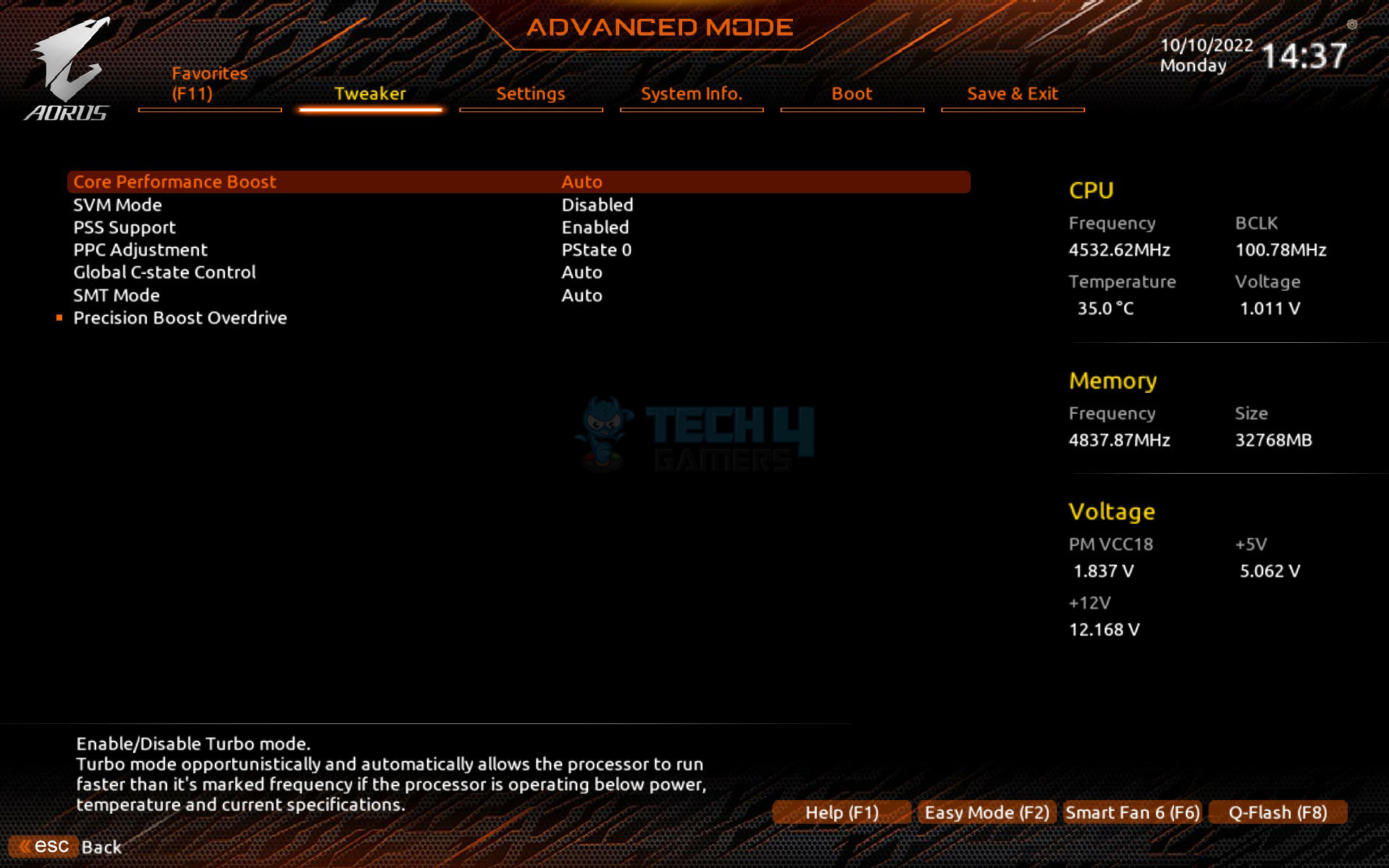
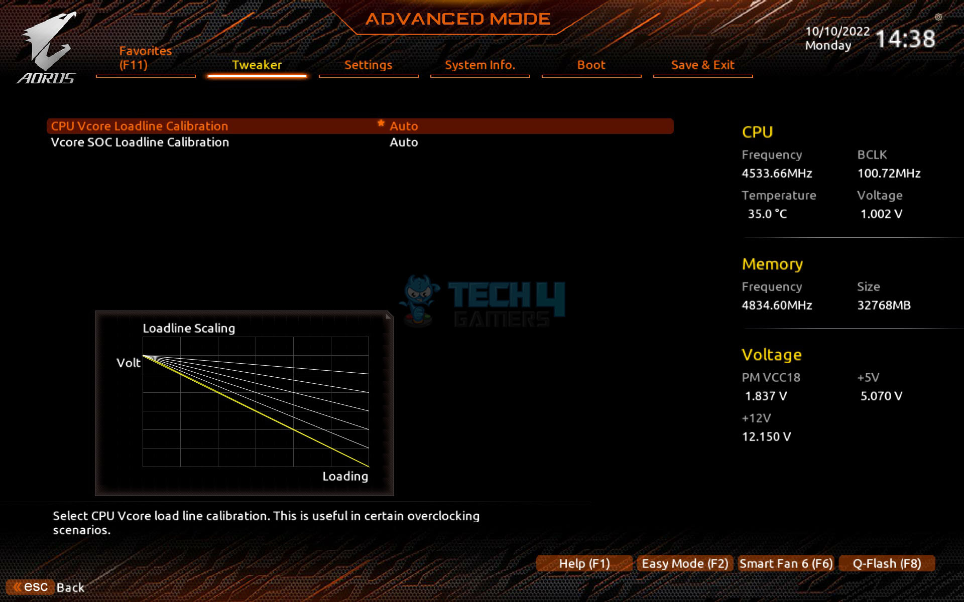
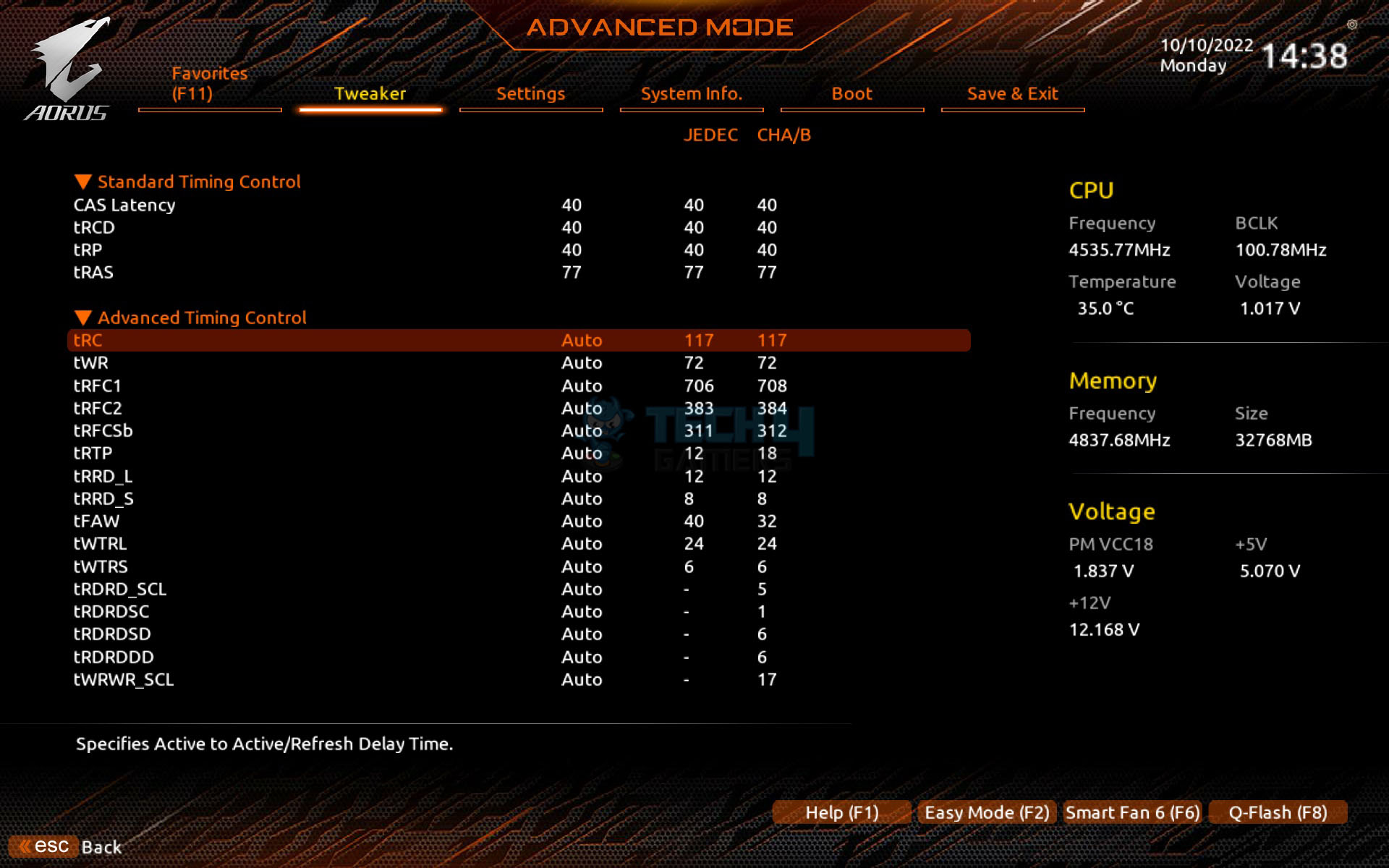
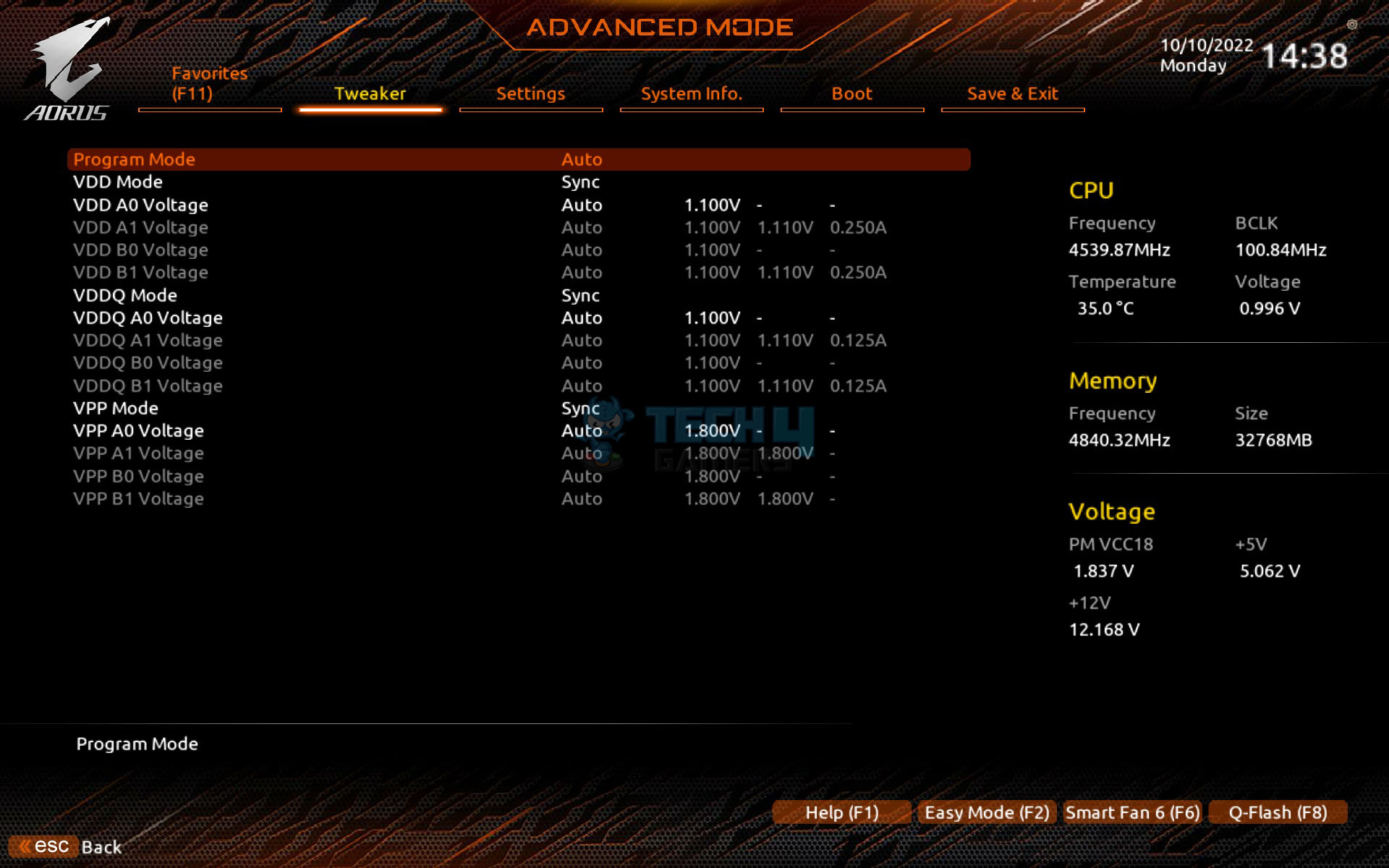

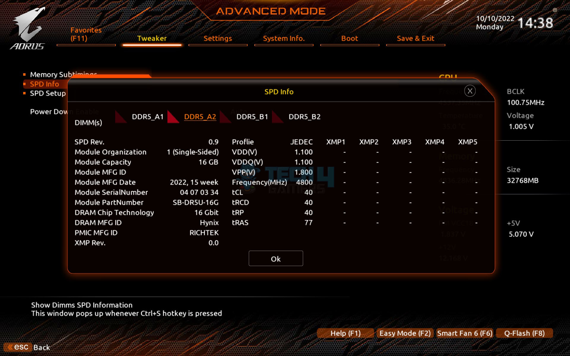
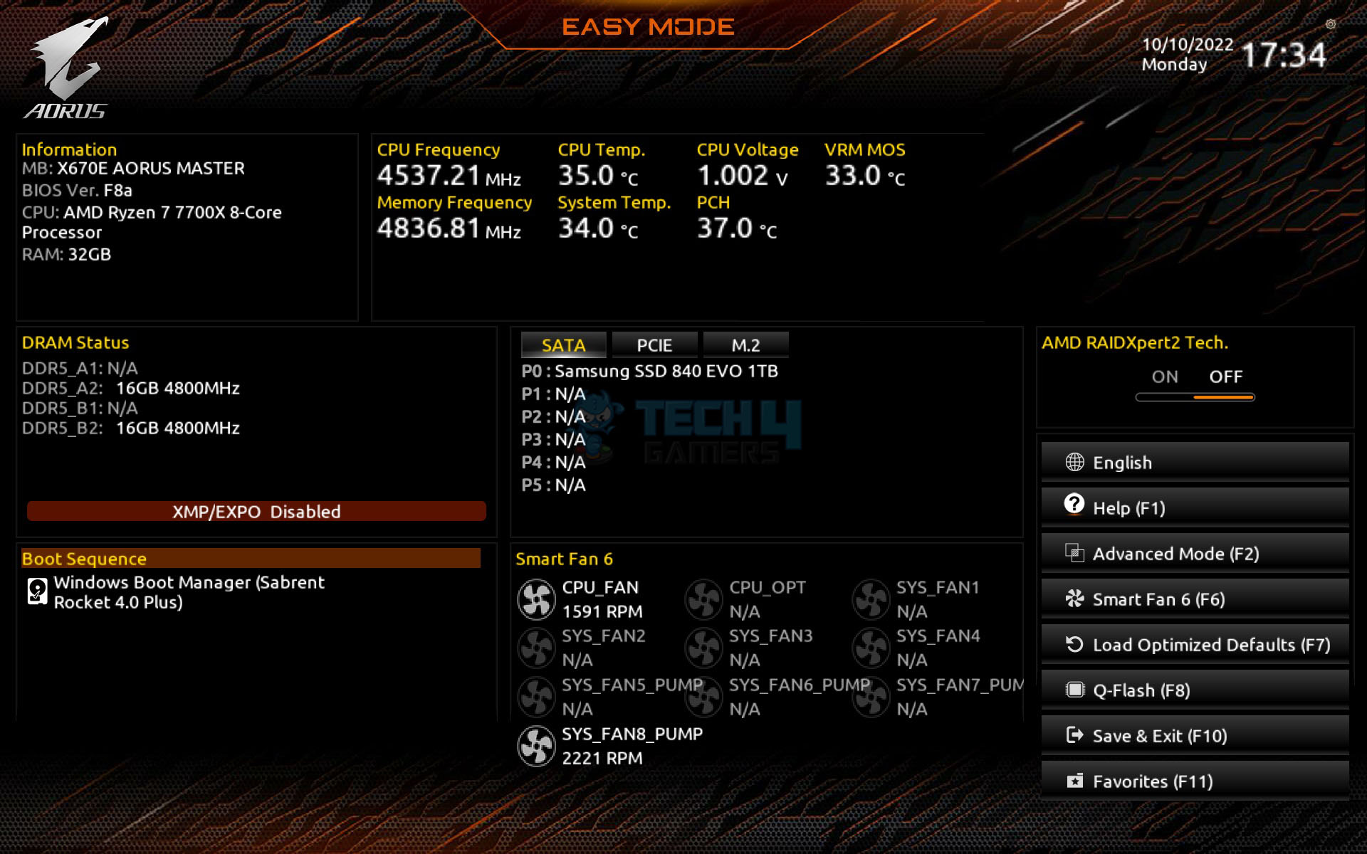


The BIOS loads in Easy mode, displaying a summary and current statistics of components. The Tweaker section is crucial for enthusiasts to tune and overclock the system, with CPU and DRAM settings on one page. It’s best to leave Infinity Fabric Frequency and Dividers on Auto for AM5, as Infinity Fabric adjusts automatically to the Memory Clock (MCLK).
However, ensure the Main Memory to Memory Controller clock is in a 1:1 ratio. AMD’s PBO options are under CPU Advanced Settings, and custom profiles can be saved for later use, even on different motherboards.
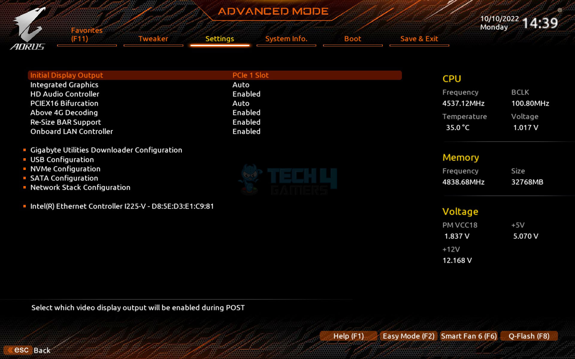
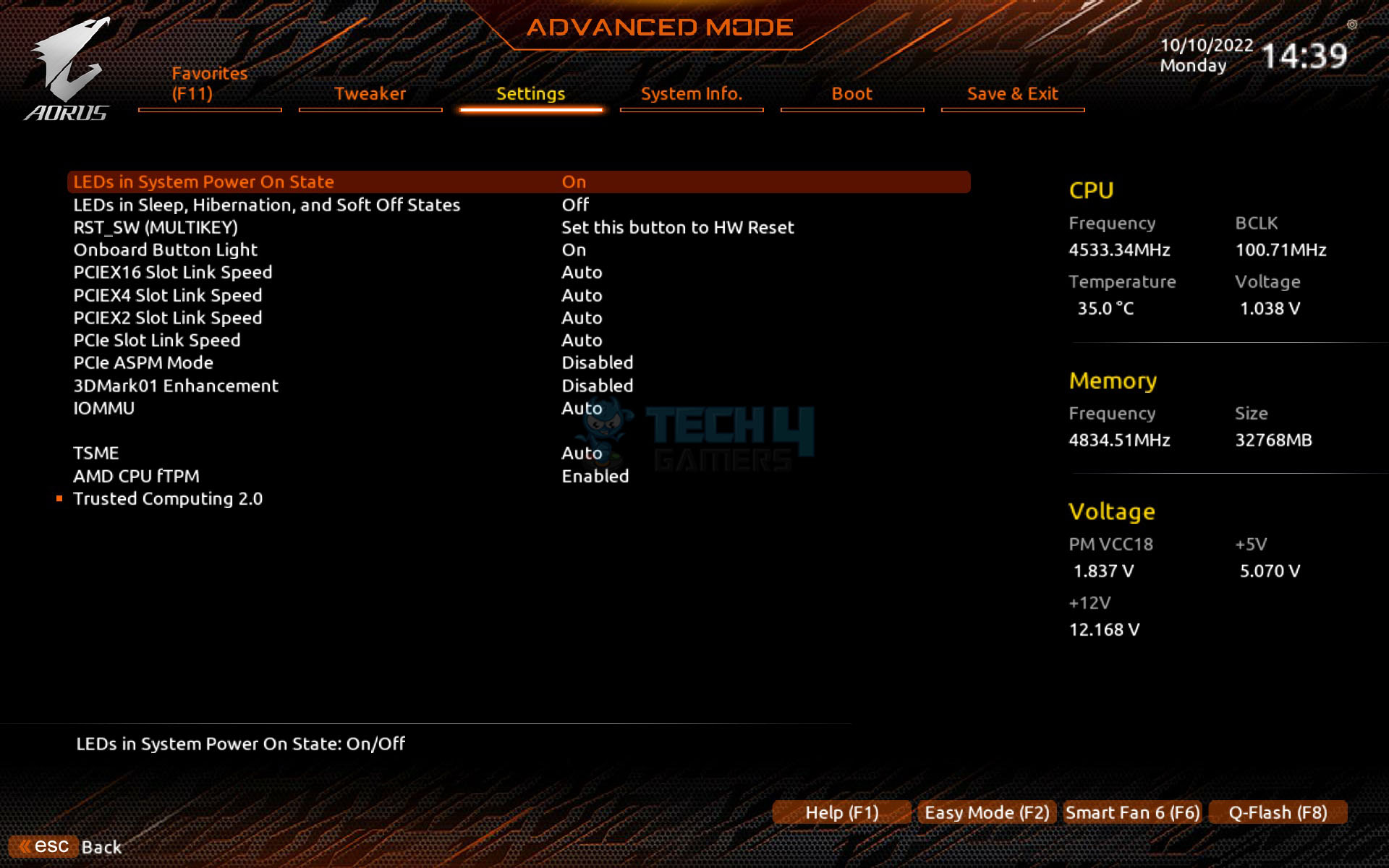
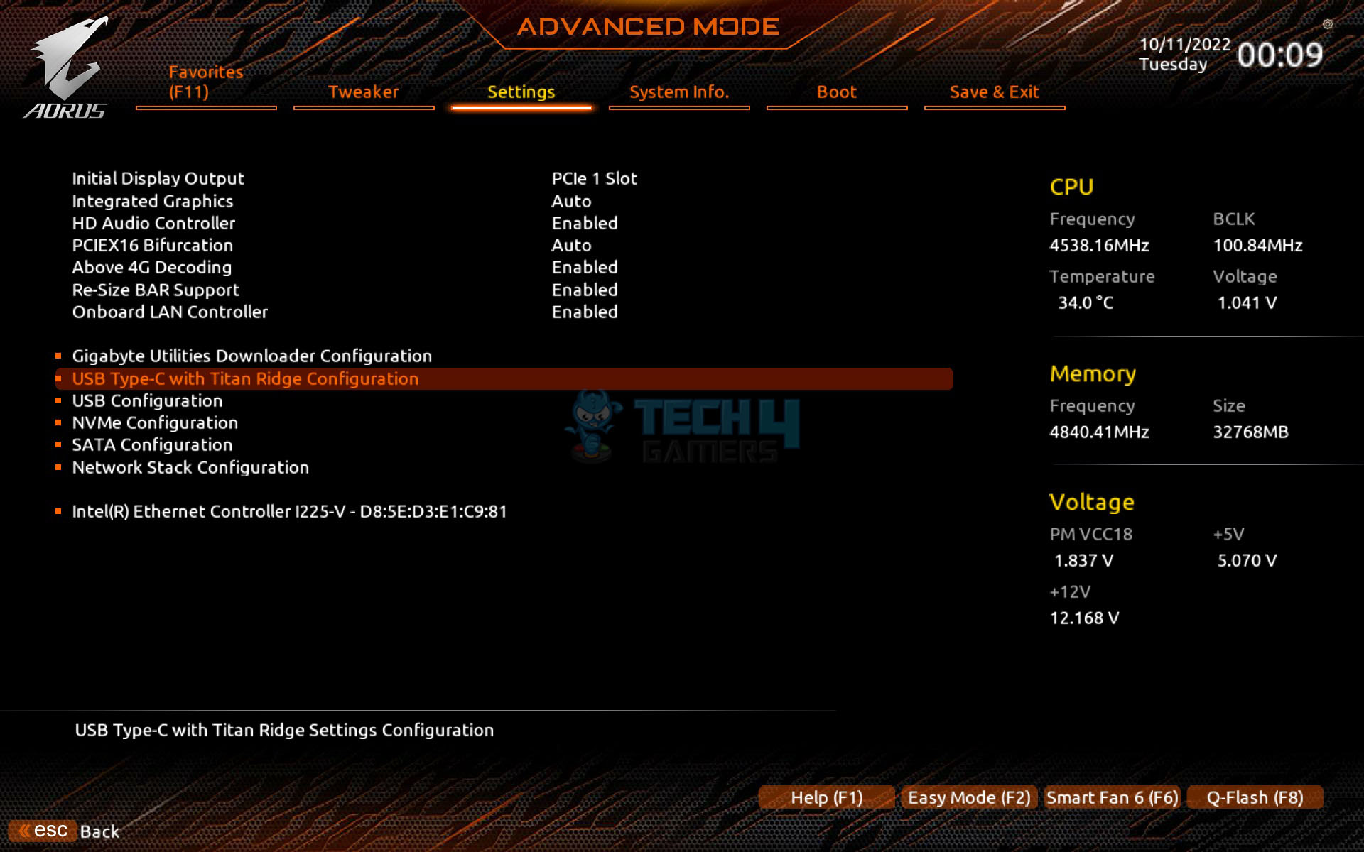
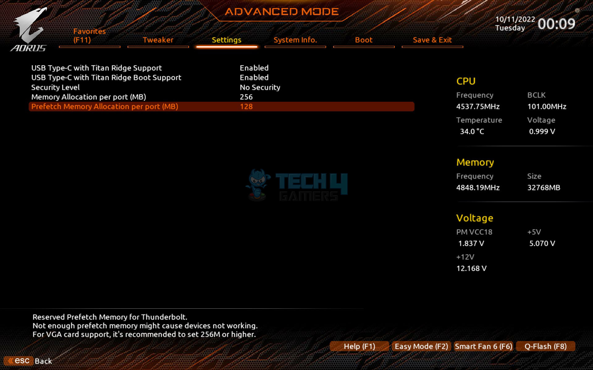
Above 4G Decoding and Re-Size Bar are enabled by default. To use the GIGABYTE Control Center, enable the Gigabyte Utilities Downloader Configuration. PCIe link speeds are set to Auto but can be manually adjusted to the correct generation.
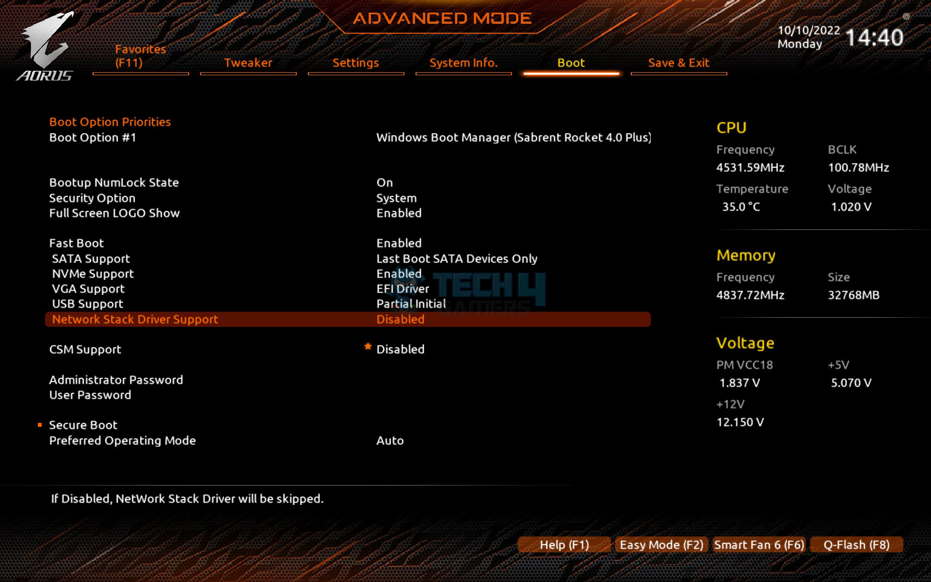
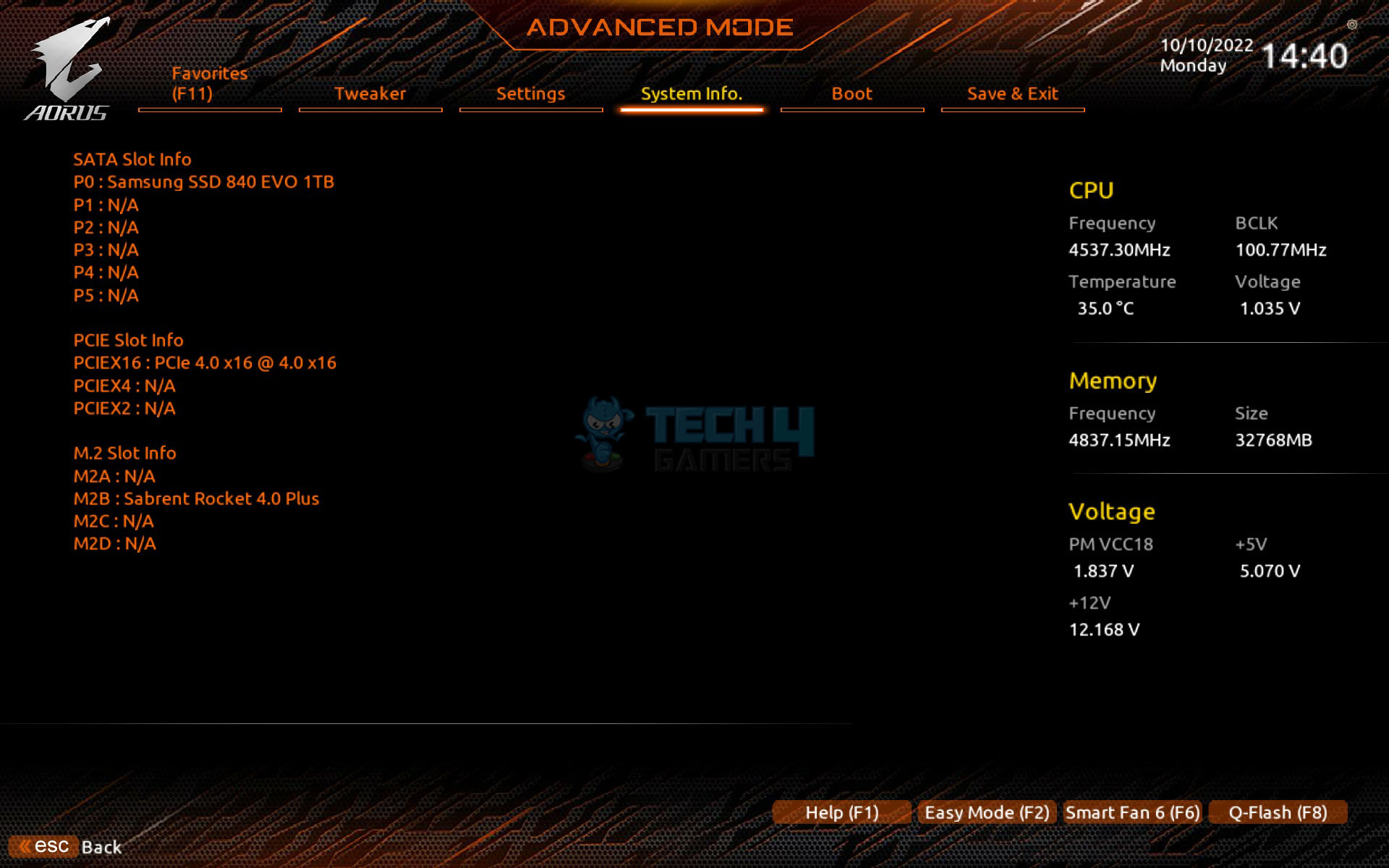
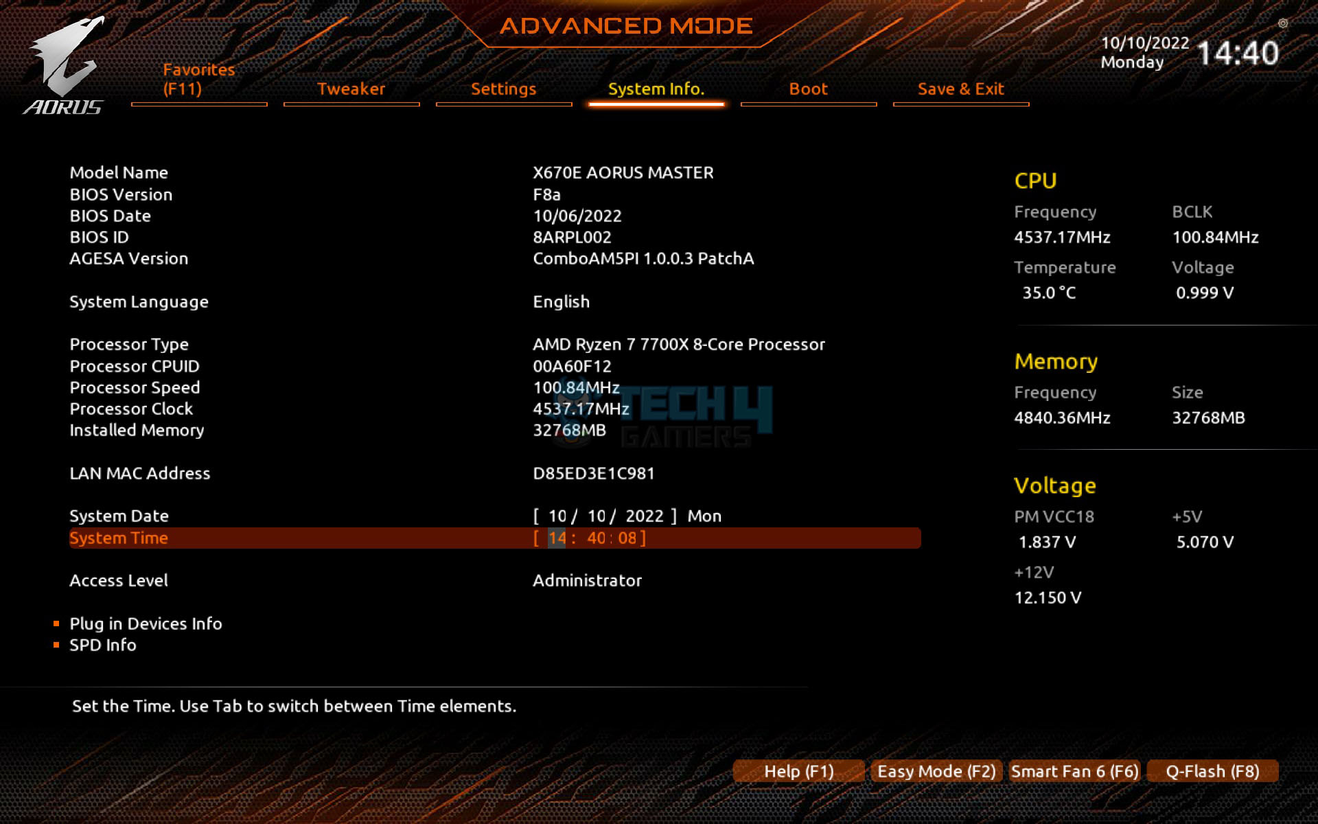
The AMD CPU fTPM, necessary for Windows 11 compatibility, is enabled by default. System Information includes Q Flash at the bottom, and you can check plugged-in devices here. The CSM is disabled under the Boot Menu to utilize the enabled Re-Size BAR feature, although the mouse speed setting is not found here.
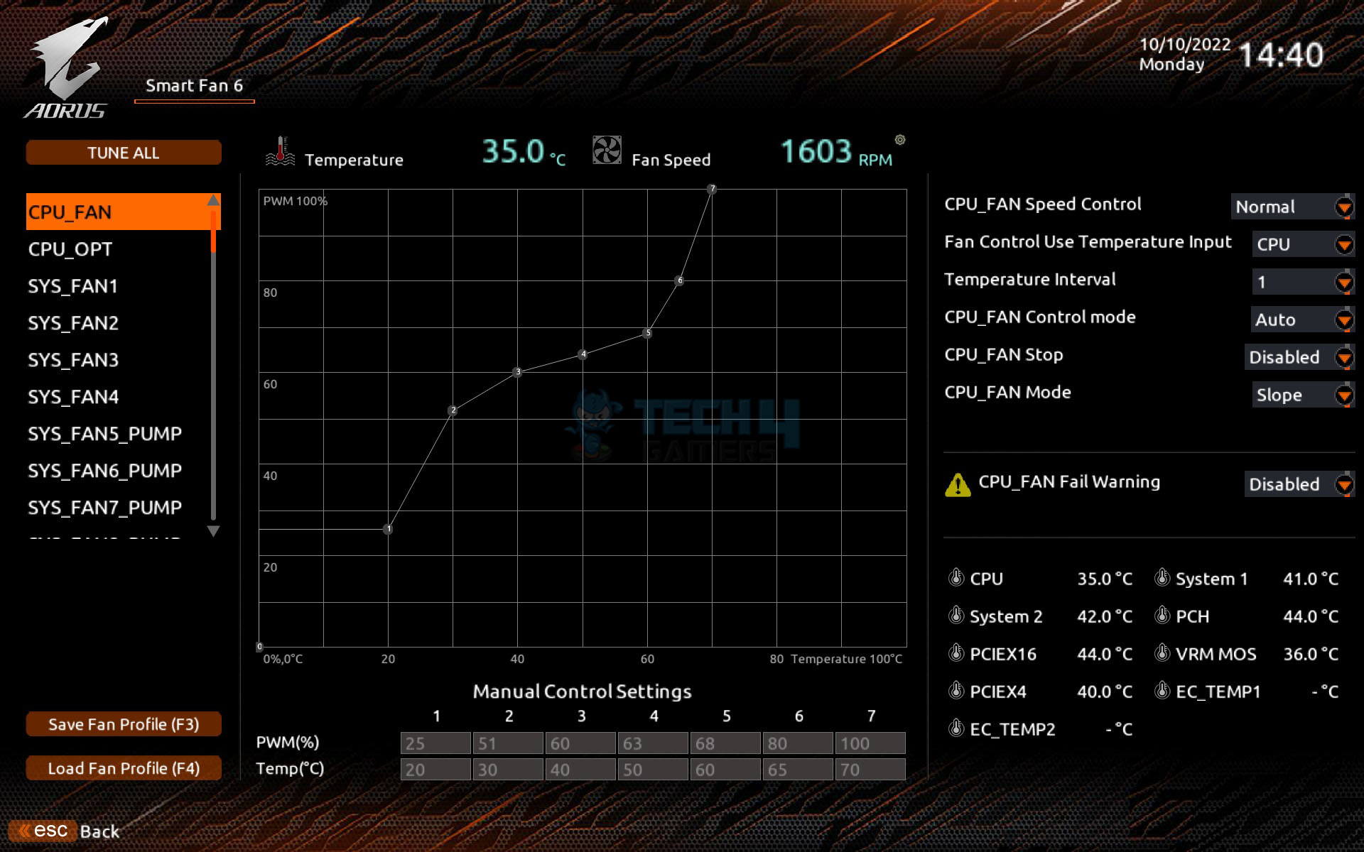
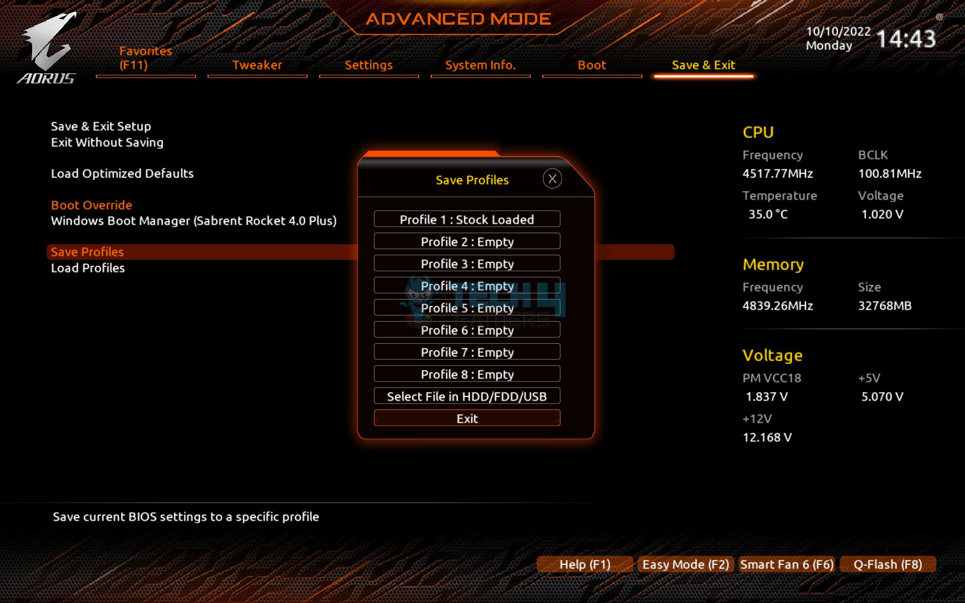
Smart Fan 6 introduces Slope and Step modes, allowing the fan to run at full speed with one click or to be set manually with a custom fan curve that can be applied to other fan headers. Pressing F3 saves fan settings in BIOS or on external media, and it is retrievable regardless of BIOS changes. The Save and Exit section lets users define profiles, load them later, and load optimized defaults.
GIGABYTE Control Center
GIGABYTE has followed the industry trend and has now merged all the related utilities under one roof called GCC. As soon as the Windows is loaded, you will be presented with an option to download the GCC. Please note that it is not yet available on the website, so your only chance is to download it when you are given the option.
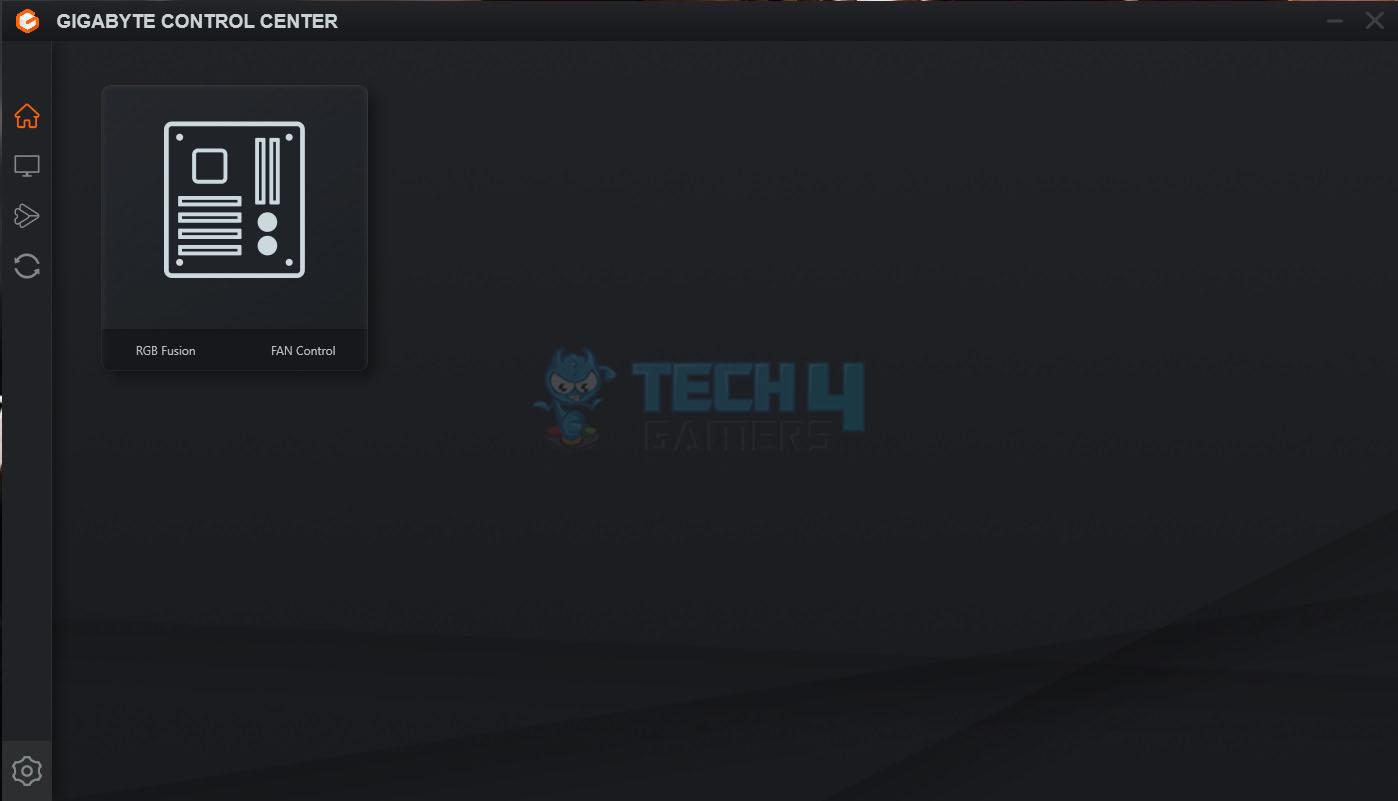
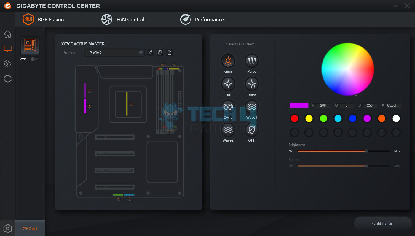
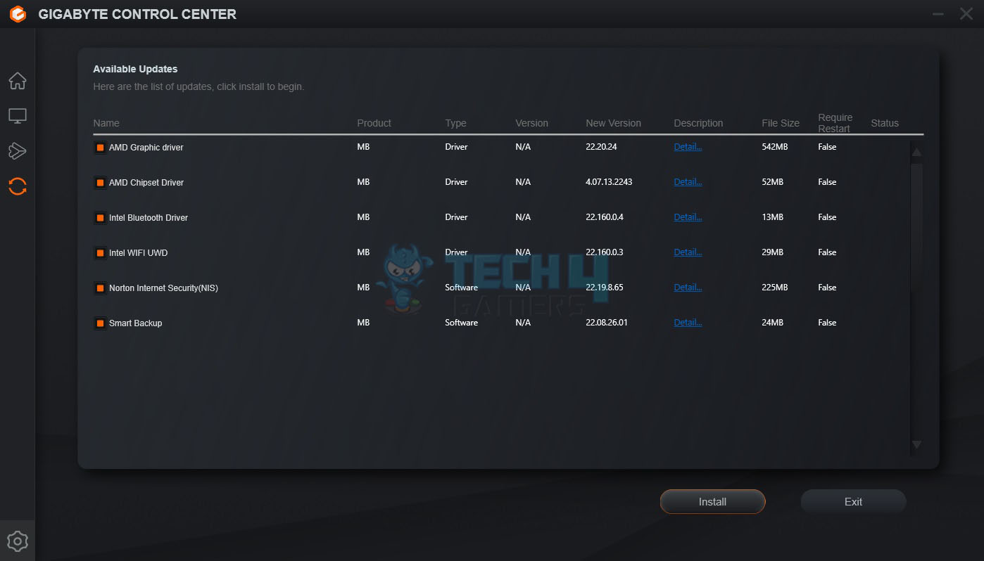
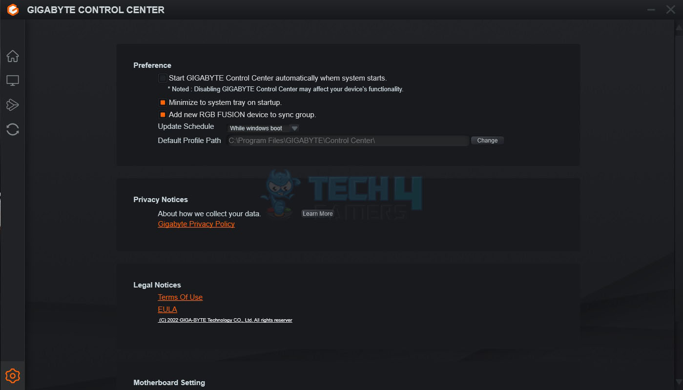
When launched, it will present you with the available updates and utilities. You can select which ones you need and start downloading them. They will be installed automatically. The main interface shows the motherboard and presents two options:
- RGB Fusion
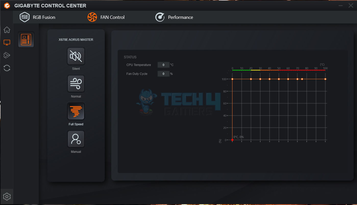
- FAN Control
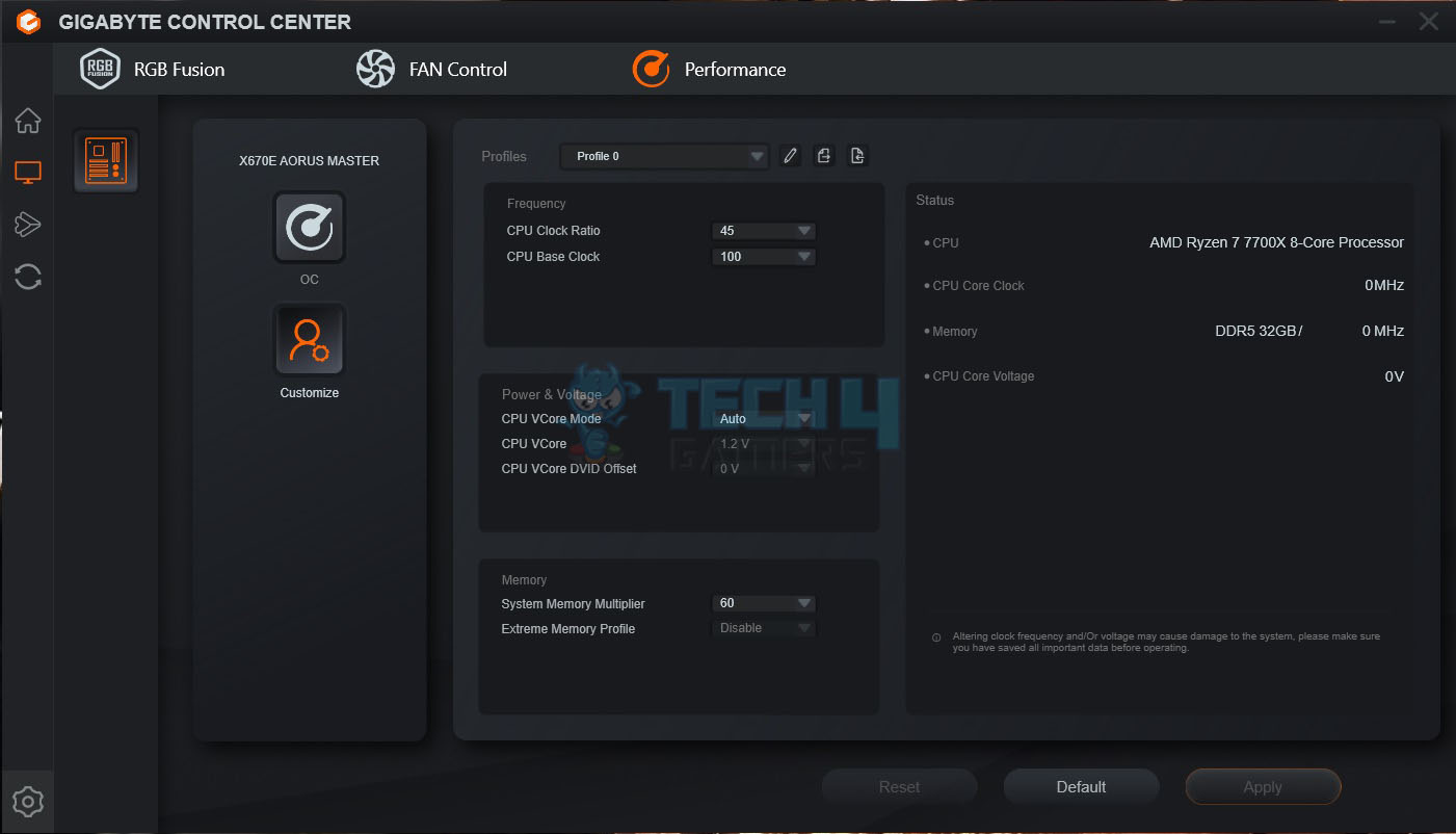
The RGB Fusion has almost the same layout as it was in the standalone version before. Remember, the onboard lighting solution is RGB (not digital). So, if you decide to sync all, the digital elements will also come in RGB mode. The user can define and control the fans’ behavior under the FAN Control option. The user can tune the system from the Performance option (but at their own risk).
Now that we have covered the UEFI/BIOS and GIGABYTE Control Center, let us turn to the testing of the motherboard.
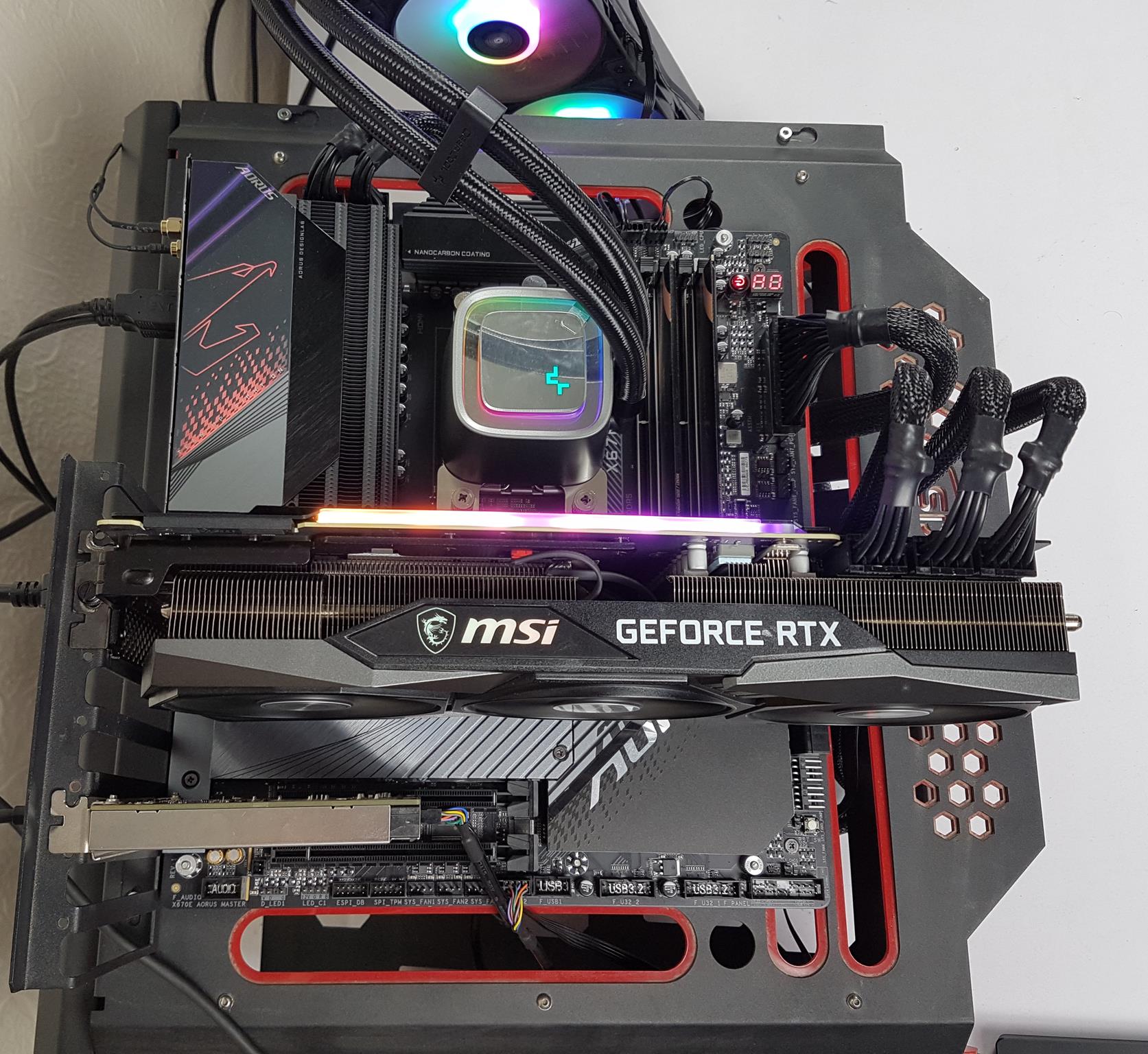
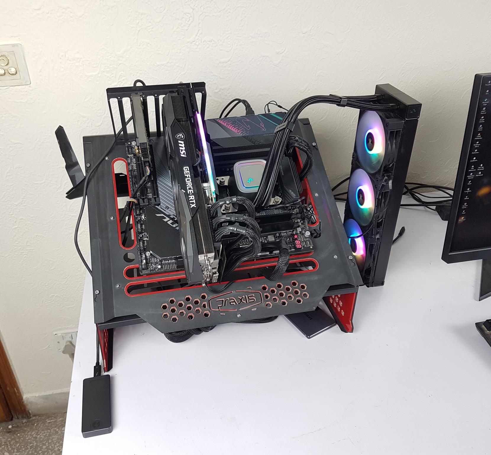
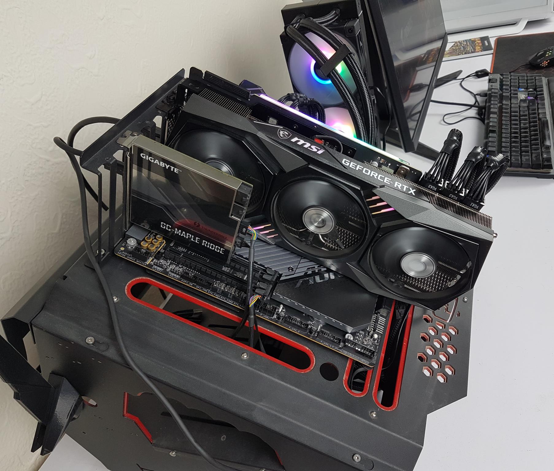
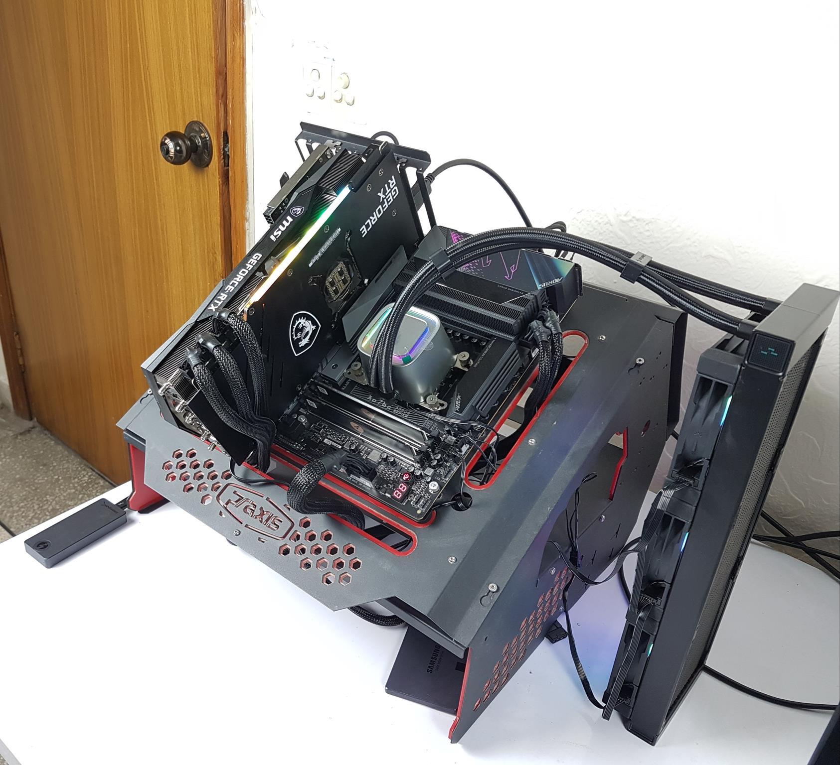
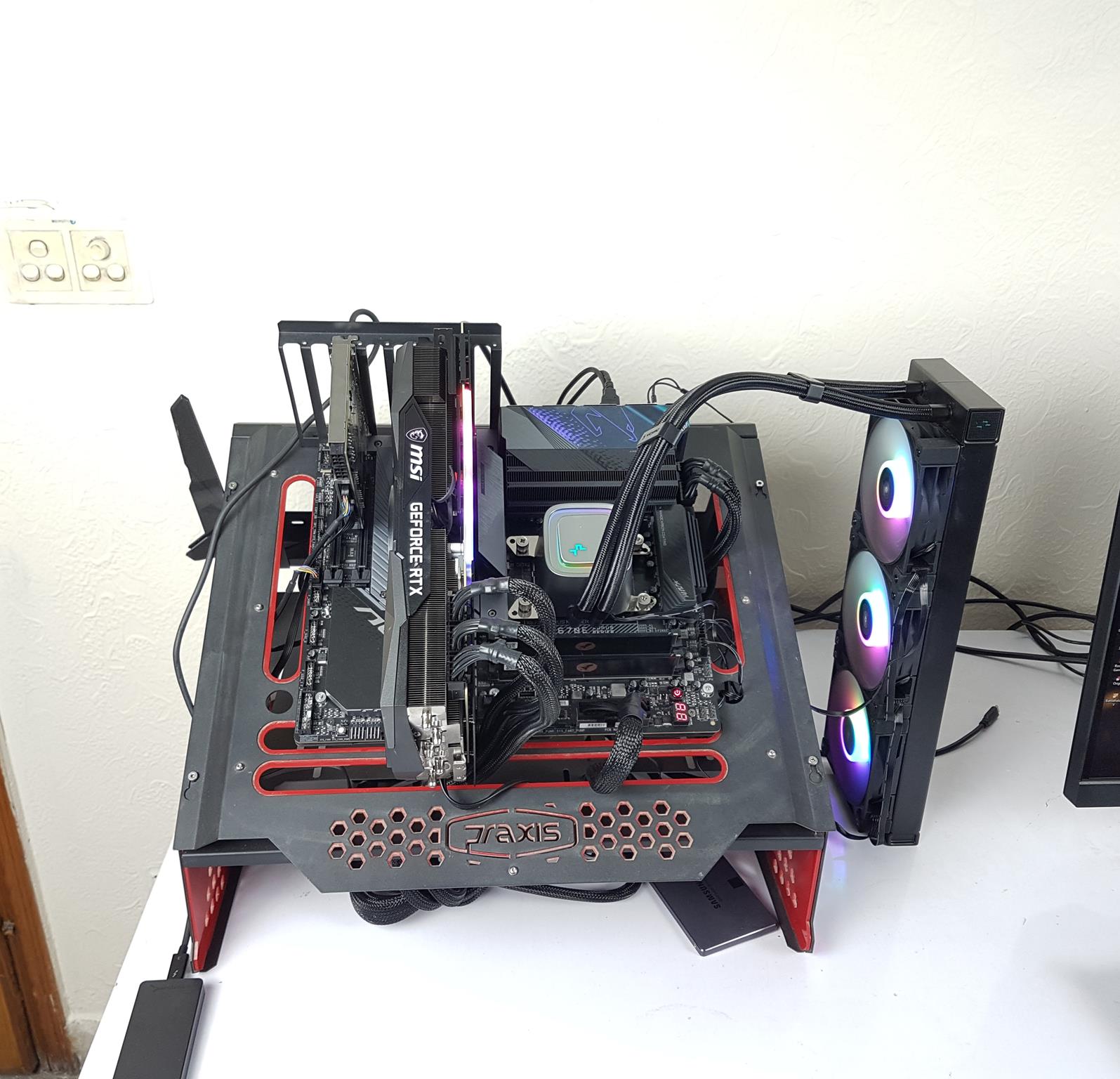
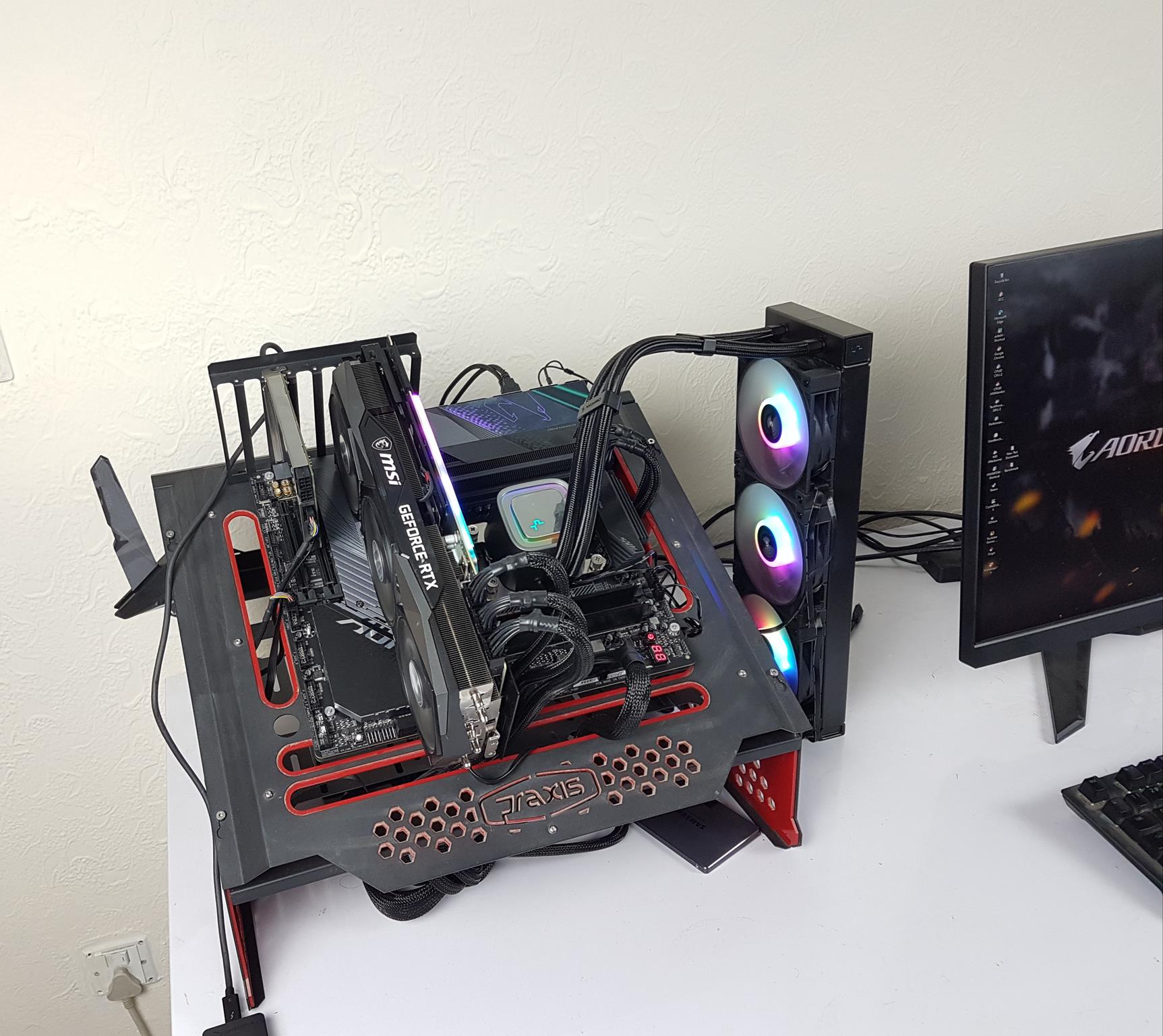
Test Setup
The following test bench setup is used to test the performance of the motherboard:
- AMD Ryzen 7 7700X [Auto, Stock]
- DeepCool LS720 [Fans and Pump at full speed]
- Sabrent Rocket 32GB DDR5 @ 4800MHz
- MSI GeForce RTX 3090 Gaming X Trio
- be quiet! Straight Power 11 1000W Platinum
- Sabrent Rocket 4 Plus 2TB PCIe 4 NVMe SSD
- Samsung 840 EVO 1 TB SSD for the Games
- Praxis Wetbench
- 2x SilverStone Air Penetrator 120SK A-RGB fans
Microsoft Windows 11 x64 Pro was used for all the testing. Nvidia 517.48 drivers were used for graphics card testing.
Following is the test suite: –
Storage Drive Tests:
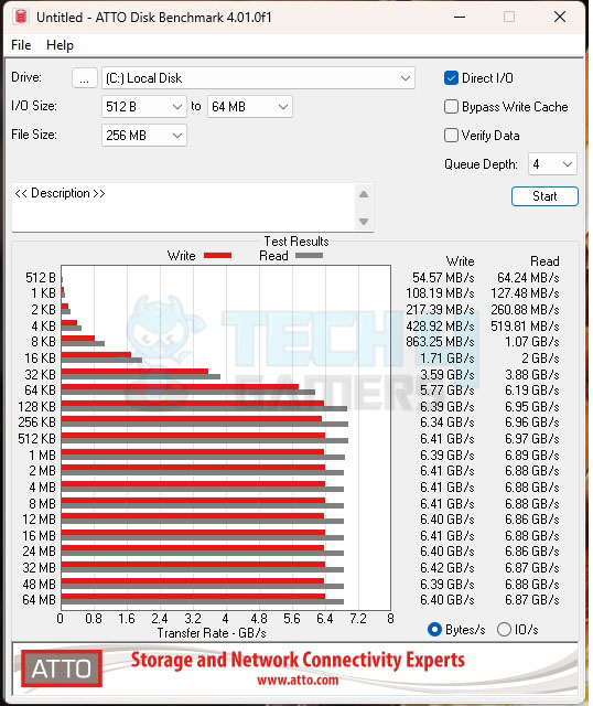
- ATTO
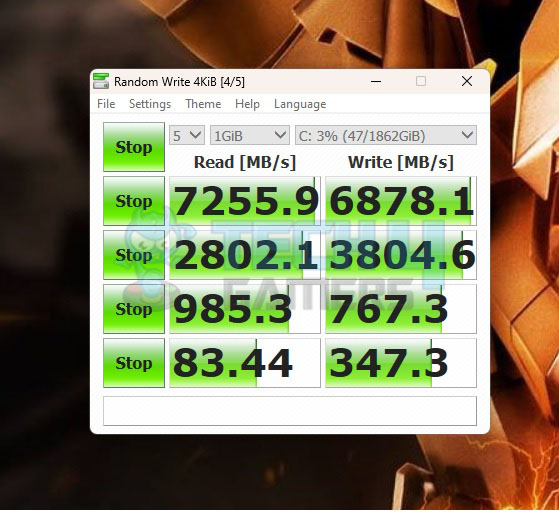
- Crystal Disk Mark
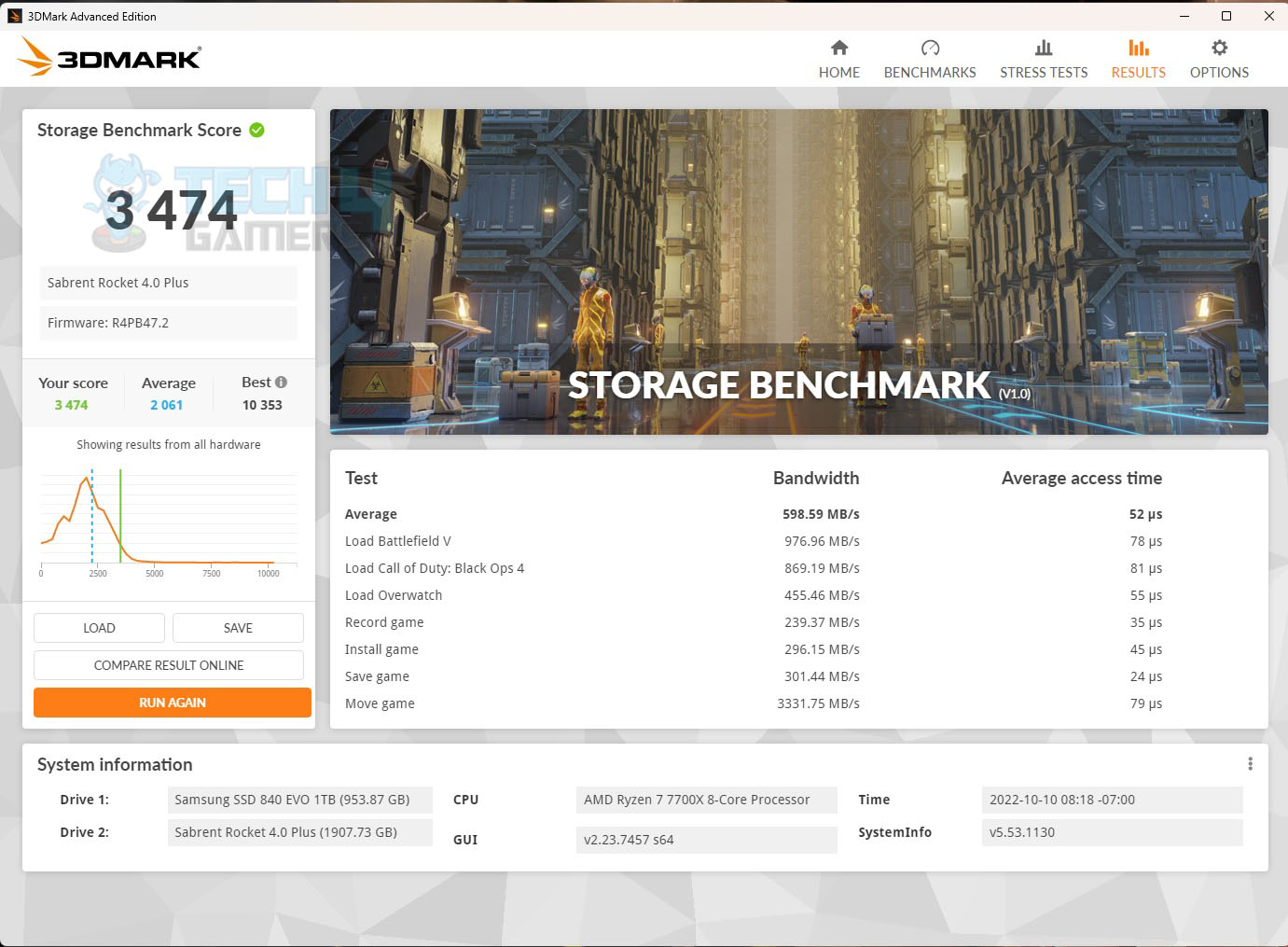
- 3DMARK Storage Test
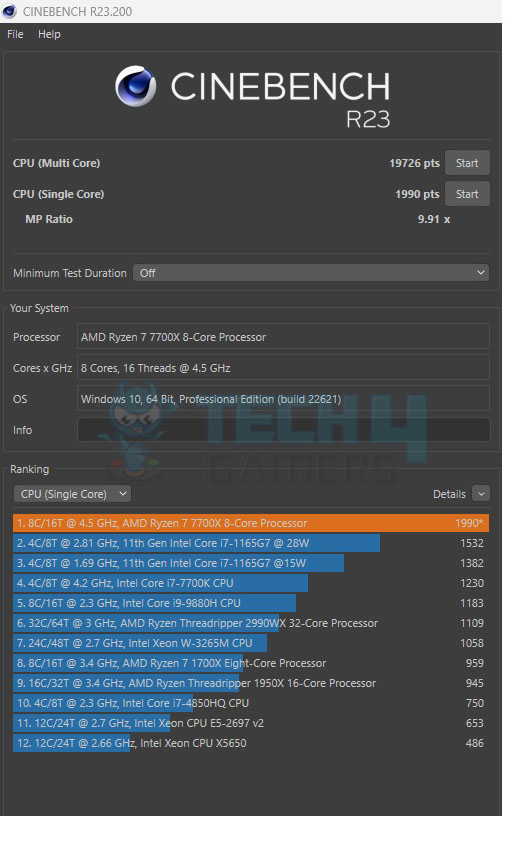
CPU Tests:
Memory Tests:
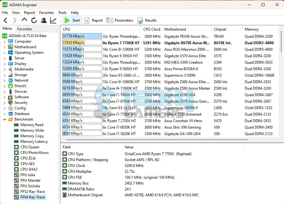
- AIDA64 Engineer
Overall System Tests:
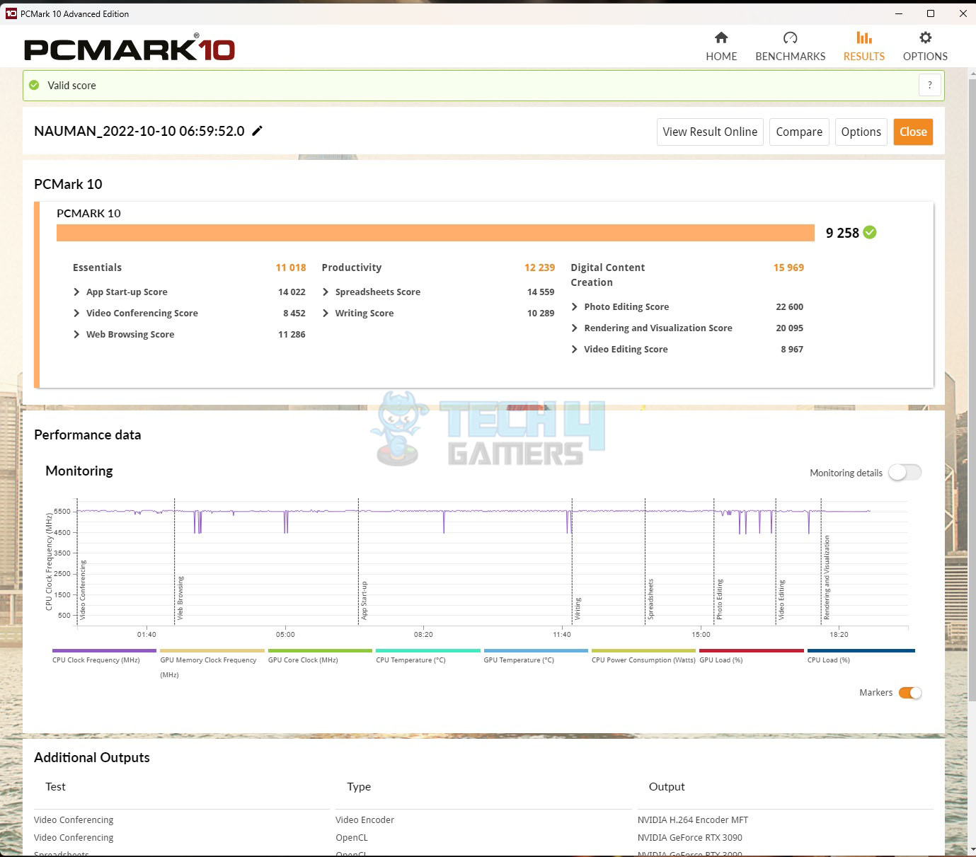
- PCMark10
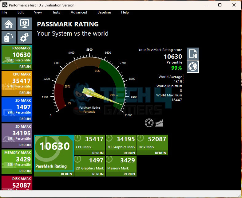
- Performance Test
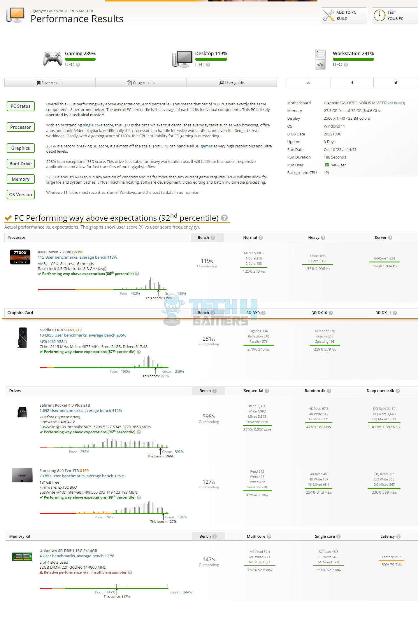
- User Benchmark
Gaming Tests:
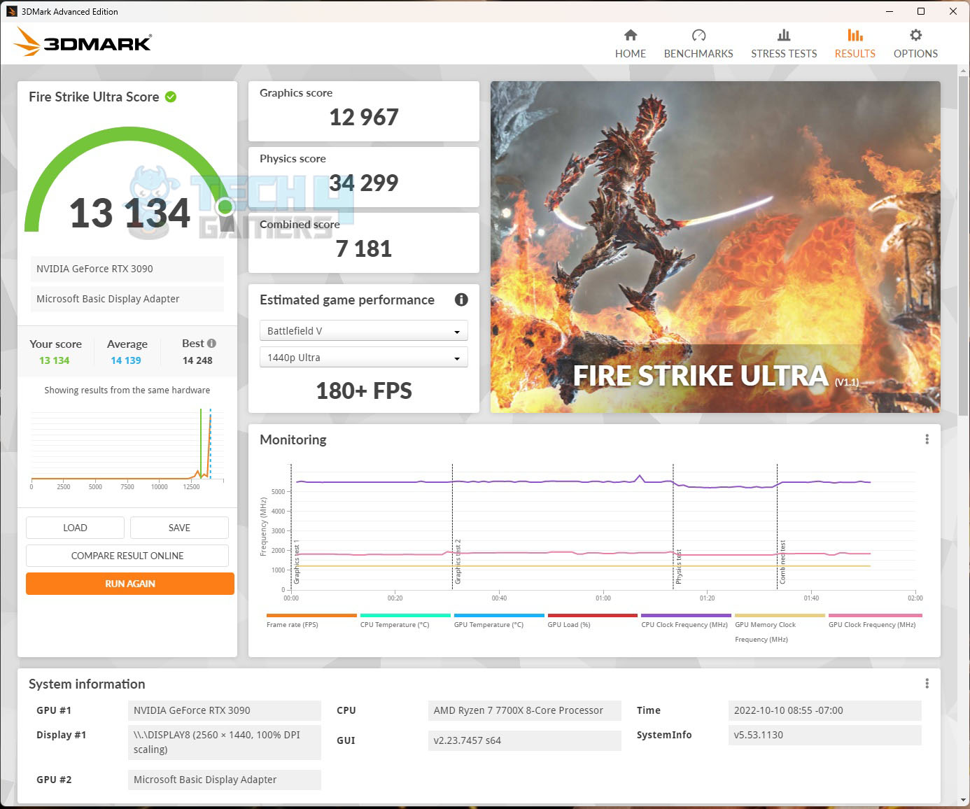
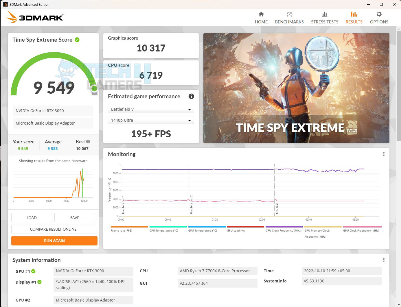
- 3DMARK
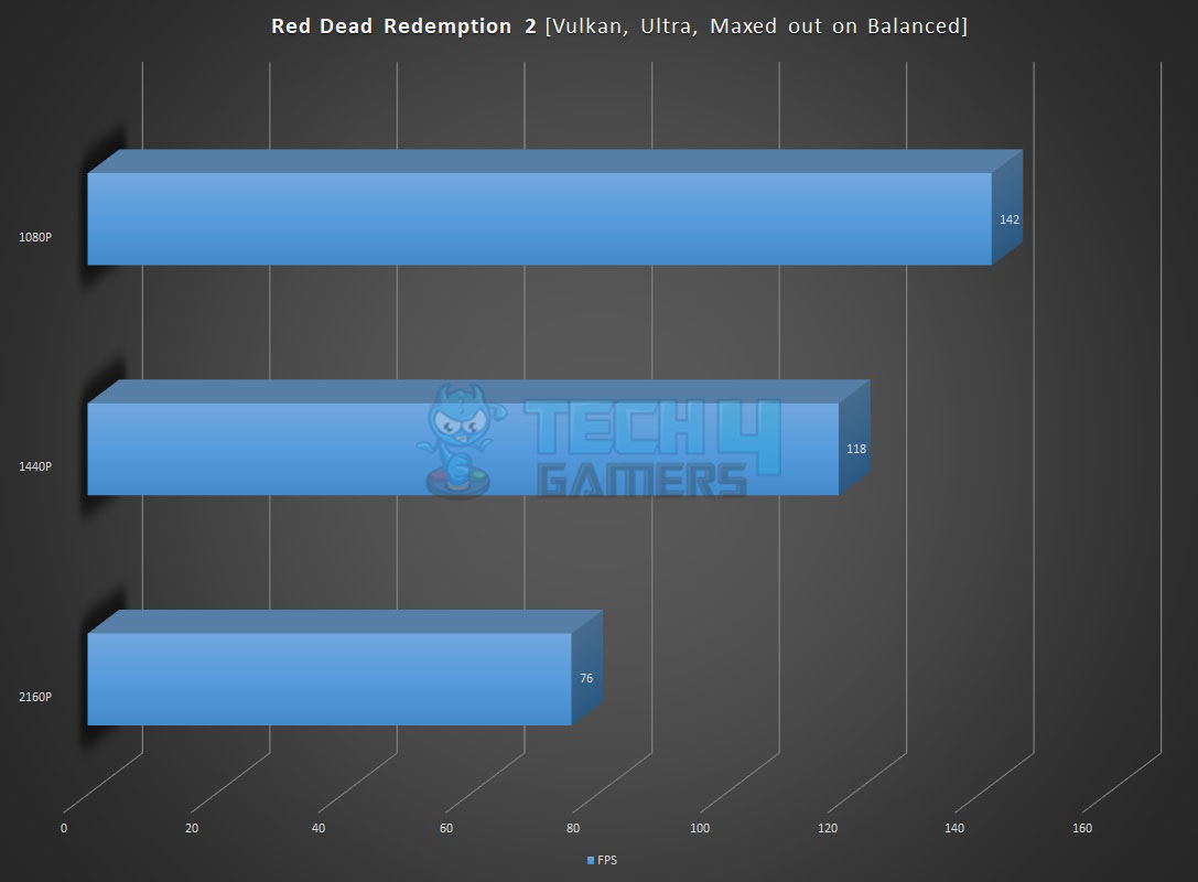
- Red Dead Redemption 2
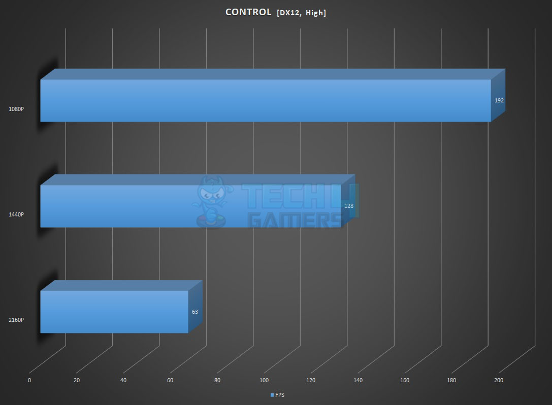
- Control
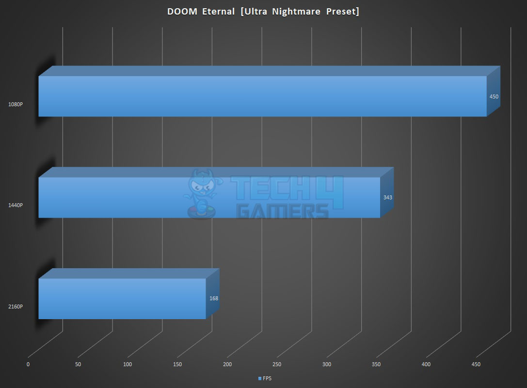
- DOOM Eternal
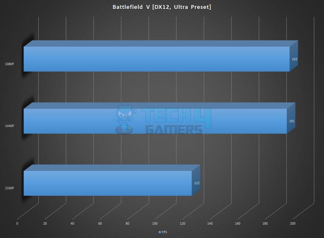
- Battlefield V
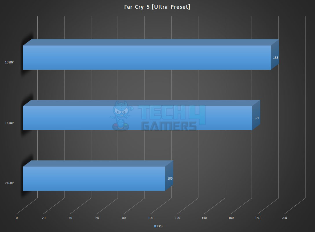
- Far Cry 5
Testing
This section will show the results of the various test suites and gaming benchmarks that we have run on this motherboard.
CPU-Z
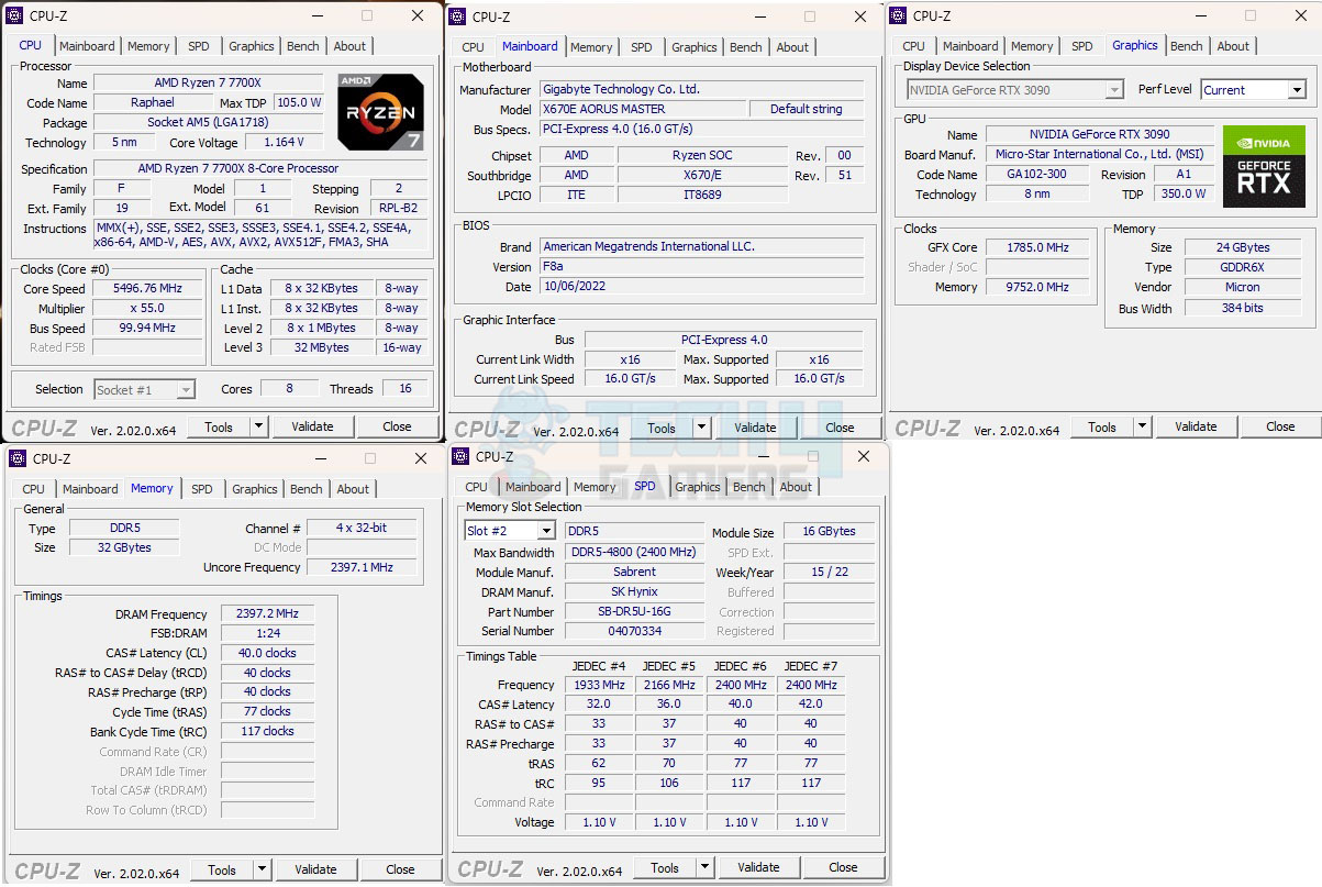
The above picture shows the CPU-Z values of the platform.
Overall System Performance
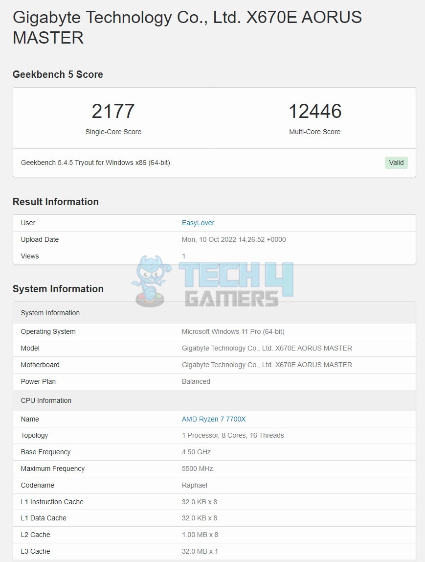
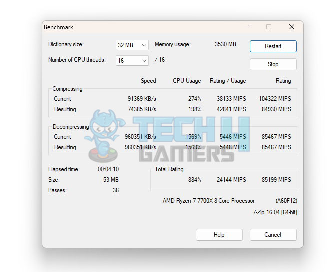
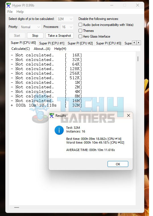
CPU Performance
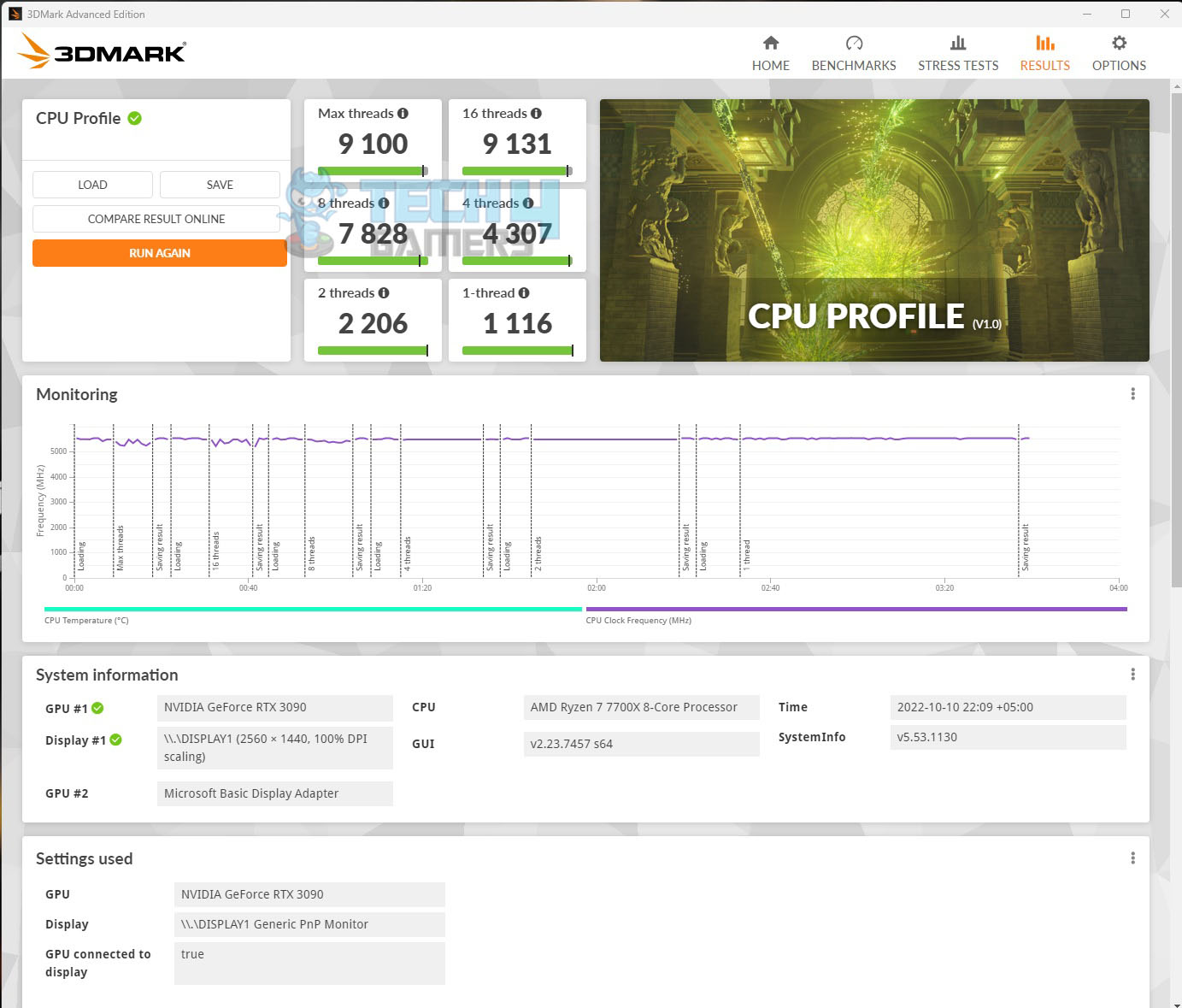
Storage Performance
Gaming Performance
Power Consumption and Thermals
We have left all the settings in the UEFI/BIOS on auto and stock. We only set the Fans and pump speed to run at 100% all the time. The motherboard picked the Memory timing and frequency correctly since the Sabrent Rocket DDR5 kits are running at JEDEC default. The power mode was Balanced in the Windows. The system was left idle for 30 minutes, with HWInfo64 running in the background and recording the values. The ambient temperature was 28°C.
| CPU | RAM | NVMe SSD | Graphics Card | |
| Idle Temp | 43.1°C | 32°C | 30°C | 46°C |
| Idle Power Draw | 16.08W [Package] | 0.250W | N/A | 81.84 (Rail) |
The frequencies on the cores were in the range of 3000MHz+
Next, the Cinebench R23 System Stability test was run for 30 minutes to record the thermals, power, and frequency behavior.
- The temperature of the CPU was 95.4°C with a VCore value of 1.428V. The frequencies were in the range of 5100MHz. The package power draw was 133.335W.
- The graphics card under gaming load was drawing near 395W power with a maximum temperature of 75° We used a custom fan curve for the graphics card so the fans were running at high speed.
- The Sabrent Rocket 4 Plus NVMe SSD was doing 58°C under load.
The SilverStone Air Penetrator 120SK A-RGB was blowing focused air toward the graphics card and NVMe ports at its full speed.
Thermal Imaging
We have used the Hti HT18 Thermal camera to record the thermals of the VRM area of the motherboard under load using the Cinebench R23 30-minute stability test on the stock settings.
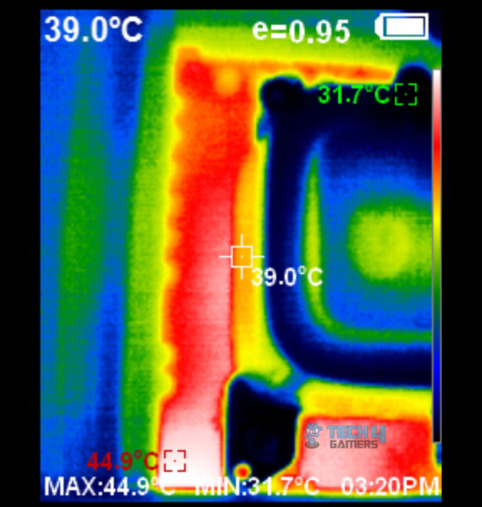
The MOSFETs were operating at around 45°C at an ambient of 29°C. The SilverStone Air Penetrator 120SK A-RGB was blowing focused air at its full speed towards the CPU socket area.
Should You Buy It?
Buy It If
✅You are a dedicated gamer: With robust power delivery, extensive cooling solutions, and support for high-speed DDR5 memory, this motherboard is perfect for those looking to build a high-performance gaming rig.
✅You want extensive USB ports: The extensive connectivity options, including multiple high-speed USB ports and dual Gen 5 M.2 slots, are beneficial for content creators who need fast data transfer and ample storage.
✅You plan on overclocking: The advanced power phases, support for memory overclocking profiles, and robust BIOS features make it ideal for users who want to push their hardware to the limits.
Don’t Buy It If
❌You’re on a budget: The premium price of this motherboard makes it less suitable for those looking to build a cost-effective PC.
Final Thoughts
The GIGABYTE X670E AORUS MASTER is a top-tier motherboard, second only to the X670E AORUS EXTREME. This E-ATX board is designed for durability and high performance, featuring an AM5 socket for AMD 7000 series CPUs and DDR5 slots with reinforced DIMM slots for stability. It offers a PCIe Gen 5 x16 slot, two additional PCIe slots, and four M.2 ports (two Gen 5 x4 and two Gen 4 x4).
Connectivity is robust with numerous USB ports, Wi-Fi 6E, Bluetooth 5.3, and an Intel 2.5GbE LAN port. For cooling, it uses Fins-Array III heatsinks with nanocarbon coating, a copper heat pipe, and high-performance thermal pads. The EZ-Latch Plus and M.2 EZ-Latch simplify hardware installation.
Audio is powered by RealTek ALC1220-VB, with 10 fan/pump headers managed by nuvoton 3947S. The power delivery system includes twin digital 16 phases with Renesas controllers and MOSFETs, ensuring stable performance.
One downside is the inconvenient placement of the CMOS battery under the chipset cover, requiring significant disassembly to access. Despite this, the motherboard excels in performance and cooling, handling all tests with ease. The USB and Thunderbolt support, along with effective cooling and stylish RGB lighting, make this a standout choice for high-end builds. Enable Low Latency Support and XMP/EXPO High Bandwidth Support in the BIOS for optimal performance.
Thank you! Please share your positive feedback. 🔋
How could we improve this post? Please Help us. 😔
Feedback By:
[Hardware Reviewer & Editor]
Meet Nauman Siddique, a highly experienced computer science graduate with more than 15 years of knowledge in technology. Nauman is an expert in the field known for his deep understanding of computer hardware.
As a tech tester, insightful reviewer, and skilled hardware editor, Nauman carefully breaks down important parts like motherboards, graphics cards, processors, PC cases, CPU coolers, and more.
- 15+ years of PC Building Experience
- 10+ years of first-hand knowledge of technology
- 7+ years of doing in-depth testing of PC Hardware
- A motivated individual with a keen interest in tech testing from multiple angles.
- I majored in Computer Science with a Masters in Marketing
- Previously worked at eXputer, EnosTech, and Appuals.
- Completed Course in Computer Systems Specialization From Illinois Tech
Get In Touch: nauman@tech4gamers.com