 Threads

The RGB LED controller modifies the voltage flowing through the wires. It handles the manual work by changing how much voltage goes to each colored LED. When you don’t have a controller, changing the colors on your LED strip is difficult and may need manual work. In case it is not functioning properly, reset the RGB controller. If it still doesn’t work, you must wire the RGB LED strip without a controller.
Key Takeaways
- You can wire RGB LED strips without a controller in different ways, like an external supply, battery pack, or Arduino microcontroller.
- Connect each color to a separate power source, like a battery or power supply, to control the individual colors.
- To get fading color effects, you can use an Arduino board.
Things to Know Before You Can Wire RGB LED Strip Without A Controller
Before attempting to wire an RGB LED strip without a controller, here are a few things to know that will help you with the techniques ahead.
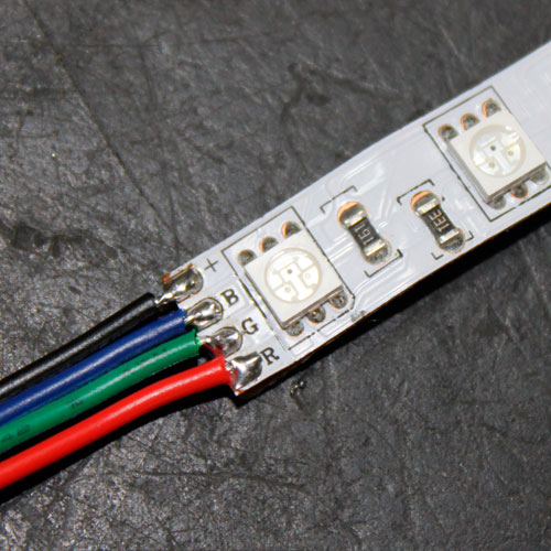
Determine The Voltage Lines
Each LED bulb typically consists of three colored wires: white or grey for the ground wire (transmitting electricity back to the circuit), red for the positive wire (carrying a positive charge), and black for the negative wire (carrying electricity).
Know The Wiring Process
Once you know what each wire in your RGB LED strip does, connect them to a power source. For each color of your RGB strip, there will be a pair or trio of wires you need to connect to a power source. That means you’ll have to connect the positive, negative, and ground wires separately for the red, green, and blue bulbs.
Data Controller Connection
The data controller is what moves the pixels to display the desired color. You can solder the end of a data connector to the RGB LED strip with some wire connectors. Once you do that, it passes signals through the wire, changing the lights based on your commands.
Identifying Wires and Connecting Them
Each light on the RGB LED strip is a pixel with three prongs: positive, negative, and ground. Connect the ground, positive, and negative wires on the power supply to those of the RGB LED strip.
How To Wire RGB LED Strip Without A Controller
Before trying out one of the methods, take some time to identify the positive and negative wires in your LED strip. You’ll also have to determine which voltage line connects to each color.
Using An External Power Supply
Use an external power supply to get specific colors when you have leftover RGB LED strips without a controller. For this method, arrange a soldering kit and a 12v power supply, such as a wall adapter. You can also use a micro USB cable for the power supply, but if it delivers a higher voltage, get a converter to avoid damaging your RGB LED strip.
Here are the steps you can follow:
- Strip the wire on the adapter cable to expose the red and black wires.
- Notice the four points labeled +12v, G, R, and B on your RGB LED strip.
- Solder the red wire, which is the positive wire, to the pad labeled +12v.
- Then, solder the black or ground wire to the pad corresponding to your desired color.
- If you want blue-colored lights, touch the ground wire to the pad labeled B; for green lights, touch it to the pad labeled G.
Mixing Colors
Of course, you won’t be limited to the primary red, blue, or green colors since this method allows you to mix colors. Just take an extra bit of wire and solder one end to the same pad as the ground wire and the other to the color you want to mix with. So, if you soldered the ground wire to the blue pad, mix it with red to get a purple effect.
Controlling Individual Colors
In case you want to control individual colors rather than sticking to a single color, you’ll have to repeat the process for each color. That means soldering a separate power supply to each color pad. Then, you can turn on the power supply that corresponds to your desired color and turn off the one you don’t want.
Wiring Your RGB LED Strip To A Battery Pack
A simpler way to control the colors of your RGB LED strip is by wiring it to a battery pack. Instead of an external power supply, I used a battery pack to power the strip.
Moreover, you will need a battery pack and clip. Connect the positive wire to the +12v pad and the ground wire to one of the color pads. On the other hand, connect a battery to each color pad on the strip instead of just a single pad to control all the colors of your RGB LED strip.
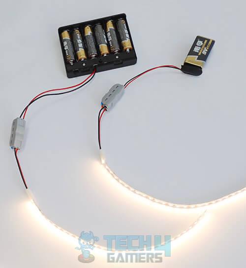
One issue I found with this method is that I could not control how brightly the colors lit up. On the other hand, you reduce the risk of frying your LEDs since the batteries will run out before the wires overheat.
Using Arduino Board
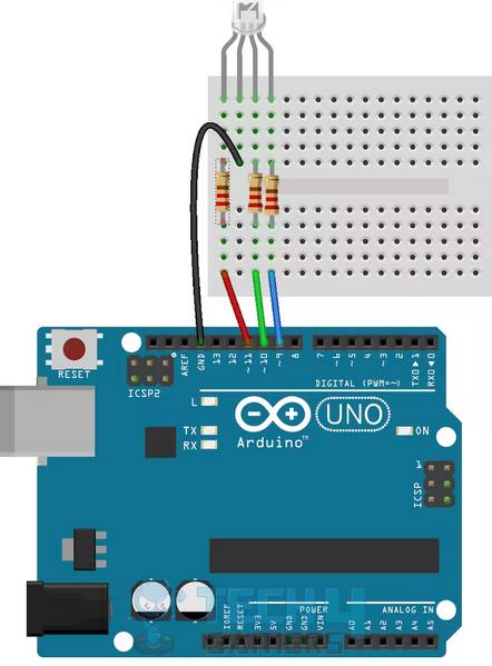
While the ways mentioned above allow you to control which color your RGB LED strip displays at a time, they can’t give you the desired effects. I tested an Arduino Microcontroller Board by directly connecting the positive, negative, and ground wires to it.
Usually, the average 12v RGB LED strips, also known as SMD5050, come with infrared remote control, but when you don’t have one, Arduino can help you get a custom fading effect.
What You’ll Need
To connect an Arduino to your 12v LED strip, gather the following parts:
- A 12v RGB LED strip
- 1 Arduino UNO Board
- 3 10k resistors
- Hookup wires
- 3 N-Channel MOSFETs (make sure they’re Logic Level)
- 12v power supply
- A breadboard
You’ll need Metal Oxide Silicon Field Effect Transistors (MOSFETs) when trying to control a component with a higher voltage than your Microcontroller, as they prevent it from overheating and frying. Namely, MOSFETs have three terminals: the source (S), drain (D), and gate (G). The voltage that passes through the gate terminal controls the current passing through the drain and source terminals.
Moreover, a major benefit of using MOSFETs is that you can pass each color of your LED strip through the MOSFET to control how bright each color on your LED strip is. I recommend getting Logic-Level MOSFETs instead of standard ones because it ensures the Arduino setup will work the way you want.
Connecting The Circuit
You can set up an Arduino and MOSFET circuit by following these steps:
- You’ll find numbered pins on the Arduino board> Connect the pins marked 5, 6, and 9 to the Gate Terminals of the three MOSFETs.
- Connect a 10k resistor in line with each gate terminal, securing each to the Ground Rail.
- Connect the Source Terminals to the Ground Rail of the board.
- Connect your LED strip’s red, blue, and green connectors to the Drain Terminals.
- Take the 12v connector of your LED strip > Connect it to the Power Rail > Connect the Ground Pin of your Arduino board to the Ground Rail.
- Take your 12v power supply > Connect it to the Power Rail.
LED strips usually come with Dupont connectors, which make it easy to connect the strip to Arduino. In case your strip doesn’t have connectors, solder the wires to your LED strip and power the board through the USB port.
Fading The Lights
Next, connect your computer to the Arduino board through a USB cable:
- Launch the Arduino IDE on your computer > Select the right port and board numbers for your board.
- Navigate first to Tools > Port and then Tools > Board. Open up a new sketch file > Save it with a suitable name.
This Arduino sketch will fade the lights on your RGB strip, one color at a time. The lights will then stay on for a few seconds before fading completely.
To make the code, you’ll have to add the following:
- Define which pins will control the MOSFETs.
- Has an overall brightness variable of 255.
- Have individual variables for each color.
- Create a variable to control how quickly the colors will fade, which we’ll call our fadeSpeed value.
- In the setup function, set the Arduino pins as the output.
- Write the code for the TurnOn() method as 3 ‘for‘ loops that take red, blue, and green lights to their maximum brightness over a particular time.
- Write the TurnOff() method code by applying the brightness variable to the red, blue, and green color pins, effectively taking them to zero over time.
Testing The Sketch
The TurnOn() and TurnOff() methods should be empty loop methods to prevent errors during compilation. In the end, your code should look like this:
#define RED_LED 6
#define BLUE_LED 5
#define GREEN_LED 9
int brightness = 255;
int gBright = 0;
int rBright = 0;
int bBright = 0;
int fadeSpeed = 10;
void setup() {
pinMode(GREEN_LED, OUTPUT);
pinMode(RED_LED, OUTPUT);
pinMode(BLUE_LED, OUTPUT);
TurnOn();
After completing the sketch, save the file, verify it, and upload it to the board. When it works, you’ll see that each color on your 12v RGB LED strip lights up individually; the white light stays for 5 seconds and then fades completely.
I found these techniques effective when I misplaced my RGB controller. Although using an Arduino board was a bit technical, I effectively achieved transition effects in RGB with the above steps. Before picking a method, determine whether you want solid colors or color effects, and proceed accordingly.
More About RGBs:
- RGB In Gaming: Everything To Know
- Explained: How To Change RGB On AMD Wraith Prism Cooler?
- How To Fix RGB Fusion Not Working [2023]
Thank you! Please share your positive feedback. 🔋
How could we improve this post? Please Help us. 😔
[How To’s & Guides Editor]
Haddi has been in the Gaming and tech Space for over 10 Years Now; he has worked on notable websites like eXputer, Gamepur, Gear Siege, Gearnuke, and plenty more. He is an expert at Games & PC Hardware; you can expect him to solve any problem. People often joke, that if there is any problem anyone can solve, Haddi can solve it faster. Currently, Haddi writes and manages a Team of Experts at Tech4Gamers.
Contact: Haddi@tech4gamers.com


